
Page 254 - Adsorbents fundamentals and applications
P. 254
CARBON NANOTUBES 239
50 nm
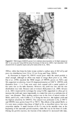
Figure 9.7. TEM image of MWNTs grown from methane decomposition on Ni-MgO catalyst at
◦
650 C, by Long and Yang (2001b) using the recipe of Chen et al. (1997). High-resolution TEM
showed 0.35 nm graphitic layers along the tubes (Chen et al., 1997).
2
2001a), while that from the latter recipe yielded a surface area of 462 m /g and
pore size distribution from 2.0 to 3.9 nm (Long and Yang, 2001b).
As illustrated in Figure 9.4, SWNT would grow when the metal particle is
small enough, although no effort was made to image them prior to ca. 1996.
Dai et al. (1996) reported the TEM images of SWNTs grown on Ni/Co and
◦
Mo supported on alumina, from CO disproportionation at 1200 C. SWNTs with
diameters from ∼1 to 5 nm were seen, each capped with a metal particle of
the same size as the tube diameter. However, the yield was low and the size
distribution was wide. Resasco and co-workers (Kitiyanan et al., 2000; Alvarez
et al., 2001) improved the technique by using Co/Mo supported on silica gel to
increase the yield and, more importantly, to control the sizes to a uniform size of
near 1 nm diameter. Their starting catalyst was in the form of mixed oxides of
MoO 3 and Co 3 O 4 , with Co/Mo = 2–4 being the best (i.e., the highest yield and
◦
the highest selectivity for SWNT). The catalyst was pretreated in H 2 at 500 C
◦
and SWNTs were grown from CO at 700 C. The effects of the added MoO 3 to
Co were more complex than those of MgO to Ni, as described above, but were
somewhat similar. A small fraction of the Co was in the metallic state at the
beginning of the nanotube growth reaction, while Mo was in the form of oxide.
During the growth reaction, the fraction of the reduced Co increased with time,