
Page 215 - Adsorption, Ion Exchange & Catalysis- 2007, Elsevier - Copy
P. 215
Else_AIEC-INGLE_cH003.qxd 7/13/2006 1:46 PM Page 211
3.8 T Fluid–Solid Fluidized Bed Reactors w o-Phase, 211
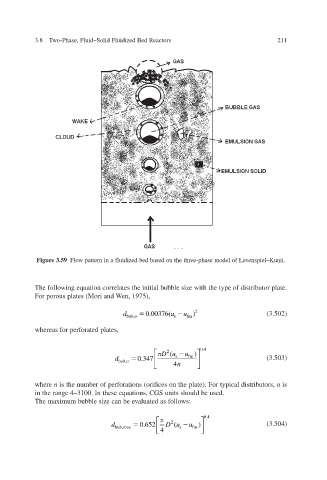
Figure 3.59 Flow pattern in a fluidized bed based on the three-phase model of Le unii. enspiel–K v
The following equation correlates the initial bubble size with the type of distributor plate.
For porous plates (Mori and en, 1975), W
d 0.00376( u) u 2 (3.502)
bub,o s fm
whereas for perforated plates,
Du ( u ) 0.4
2
d 0.347 s fm (3.503)
bub,o
n 4
where n is the number of perforations (orifices on the plate). For typical distrib utors, n is
in the range 4–3100. In these equations, CGS units should be used.
The maximum bubble size can be e v aluated as follo ws:
0.4
2
d 0.652 D u ( u ) (3.504)
bub,ma x 4 s fm 