
Page 223 - Adsorption, Ion Exchange & Catalysis- 2007, Elsevier - Copy
P. 223
Else_AIEC-INGLE_cH003.qxd 7/13/2006 1:46 PM Page 219
3.8 T Fluid–Solid Fluidized Bed Reactors w o-Phase, 219
where:
eS the volume fraction of the dense phase occupied by solids ( )
1
fm
eS
C o the feed concentration of the gas
A the cross-sectional area of the bed
Z f the fluidized-bed height
Q G the volumetric flow rate of gas through the reactor .
Gas in the emulsion phase in plug flo w In this case, the following are assumed: (a)
two-phase theory applies (bubble and particulate phases), (b) plug flow of gas throughout
the reactor i.e. in the bubble and emulsion phase. This model is referred to as the “tw o-
,
phase model” with plug emulsion phase (Kelkar and Ng, 2002).
For the bubble phase (gas phase),
C d
f u b L C ( C ) r ( ) 0 (3.519)
bub s be b p bub b b,vs
z d
where:
L b in (m 3 gas interchange v olume/m 3 of reactor) (1/s)
b the volume fraction of bubble occupied by solids
(– r b,vs ) the reaction rate in bubbles per unit volume of solids, based on the
reactant
f bub the fraction of the gas flow carried by the bubble phase
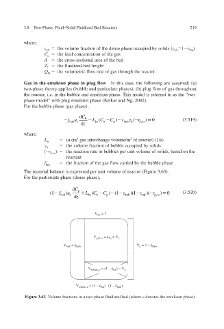
The material balance is expressed per unit volume of reactor (Figure 3.63).
For the particulate phase (dense phase),
d C p
(1 f ) u L ( C C ) (1 )(1 )( )r 0 (3.520)
bub s be b p bub mf p,vs
d z
V tot = 1
V gas, e = ε × V e
fm
V bub = ε bub V e = 1 – ε bub
V solids, e = (1 – ε ) × V e
fm
V solids, e = (1 – ε ) (1 – ε bub )
fm
Figure 3.63 Volume fractions in a two-phase fluidized bed (where e denotes the emulsion phase).