
Page 256 - Advanced Design Examples of Seismic Retrofit of Structures
P. 256
Example of a Steel Frame Building With Masonry Infill Walls Chapter 4 249
P UF
For < 0:2
P CL
(4.33)
P UF M x M y
+ + 1:0
2P CL m x M CEx m y M CEy
where:
P UF ¼axial force in the member;
P CL ¼lower-bound compression strength of the column;
M x ¼bending moment in the member for the x-axis;
M y ¼bending moment in the member for the y-axis;
M CEx ¼expected bending strength of the column for the x-axis;
M CEy ¼expected bending strength of the column for the y-axis;
m x ¼value of m for the column bending about the x-axis in accordance with
Table 4.16; and
m y ¼value of m for the column bending about the y-axis in accordance with
Table 4.16.
Steel columns with axial compressive forces exceeding 50% of the lower-bound
axial compressive strength, P CL , shall be considered force-controlled for both
axial loads and flexure and shall be evaluated using Eq. (4.34):
P UF M UFx M UFy
+ + 1:0 (4.34)
P CL M CLx M CLy
where:
M UFx ¼bending moment in the member for the x-axis;
M UFy ¼bending moment in the member for the y-axis;
M CLx ¼lower-bound bending strength of the column for the x-axis; and
M CLy ¼lower-bound bending strength of the column for the y-axis.
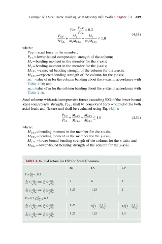
TABLE 4.16 m-Factors for LSP for Steel Columns
IO LS CP
For P UF < 0:2
P CL
b f 52 h 300 2 6 8
ffiffiffiffiffip and ffiffiffiffiffip
2t f F ye t w F ye
b f 65 and h 460 1.25 1.25 2
ffiffiffiffiffip ffiffiffiffiffip
2t f t w
F ye F ye
P UF 0:5
For0:2
P CL
b f 52 h 300 1.25 5 P 5 P
ffiffiffiffiffip and ffiffiffiffiffip
2t f t w 91 12 1
F ye F ye 3P CL 3P CL
b f 65 h 400 1.25 1.25 1.5
ffiffiffiffiffip and ffiffiffiffiffip
2t f F ye t w F ye