
Page 259 - Advanced Design Examples of Seismic Retrofit of Structures
P. 259
252 Advanced Design Examples of Seismic Retrofit of Structures
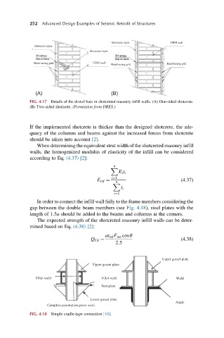
Shotcrete layer URM wall
Shotcrete layer
Shotcrete layer
Reinforcing grid URM wall Reinforcing grid Reinforcing grid
(A) (B)
FIG. 4.17 Details of the dowel bars in shotcreted masonry infill walls. (A) One-sided shotcrete.
(B) Two-sided shotcrete. (Permission from DRES.)
If the implemented shotcrete is thicker than the designed shotcrete, the ade-
quacy of the columns and beams against the increased forces from shotcrete
should be taken into account [2].
When determining the equivalent strut width of the shotcreted masonry infill
walls, the homogenized modulus of elasticity of the infill can be considered
according to Eq. (4.37) [2]:
n
X
E i t i
i¼1
E inf ¼ (4.37)
n
X
t i
i¼1
In order to connect the infill wall fully to the frame members considering the
gap between the double beam members (see Fig. 4.18), steel plates with the
length of 1.5a should be added to the beams and columns at the corners.
The expected strength of the shotcreted masonry infill walls can be deter-
mined based on Eq. (4.38) [2]:
at inf F me cosθ
Q CE ¼ (4.38)
2:5
Upper gusset plate
Upper gusset plate
Fillet weld Fillet weld Weld
Seat plate
Lower gusset plate
Angle
Complete penetration grove weld
FIG. 4.18 Simple cradle-type connection [10].