
Page 278 - Advanced Design Examples of Seismic Retrofit of Structures
P. 278
Example of a Steel Frame Building With Masonry Infill Walls Chapter 4 271
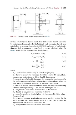
FIG. 4.24 The retrofit details of the cradle-type connections [12a].
in-plane direction (even at experienced lateral drifts equal to the drift acceptable
by the design performance level of the building), while preventing the wall from
out-of-plane overturning. According to ASCE 41, anchorage of walls to dia-
phragms shall be evaluated or retrofitted for forces calculated using Eq.
(4.46), which shall be developed into the diaphragm.
F p ¼ 0:4S XS k a k h χW p (4.46)
(4.47)
F p,min ¼ 0:2k a χW p
L f
k a ¼ 1:0+ (4.48)
30:48
1 2z a
k h ¼ 1+ (4.49)
3 h h
where:
F p ¼seismic force for anchorage of walls to diaphragms;
k a ¼factor to account for diaphragm flexibility, equal to 1.0 for rigid dia-
phragms and need not exceed 2.0 for flexible diaphragms;
L f ¼span, in feet, of a flexible diaphragm that provides the lateral support for
the wall between vertical primary seismic-force-resisting elements that pro-
vide lateral support to the diaphragm in the direction considered;
k h ¼factor to account for variation in force over the height of the building
when all diaphragms are rigid—for flexible diaphragms, use 1.0;
z a ¼height of the wall anchor above the base of the structure;
h h ¼height, in feet, above the base to the roof level;
χ¼factor for calculation of out-of-plane wall forces, equal to 1.3 for LS per-
formance level;
S XS ¼spectral response acceleration parameter at short periods for the
selected hazard level and damping, adjusted for site class, without any
adjustment for soil–structure interaction; and
W p ¼weight of the wall tributary to the wall anchor.