
Page 437 - Advanced Design Examples of Seismic Retrofit of Structures
P. 437
384 Advanced Design Examples of Seismic Retrofit of Structures
21 22 ø12@25cm (New) ø20@20cm (New)
ø12@25cm (New) ø20@20cm (New) 15 260 15 L=290cm 22 Continuous 5
15 260 15 L=290cm 22 Continuous 20 T.O.F(NEW)=–30
T.O.F(NEW)=–30
T.O.F=–55
ø20@20cm (New)
25 T.O.F=–55 6 Continuous 25
ø20@20cm (New)
2 3 ø20@20cm (New) Continuous
ø20@7.5cm (New) ø20@7.5cm (New) 5 Continuous 50 ø20@20cm (New)
90 50 90
1 Continuous Continuous 1 Continuous
L=125cm
L=125cm
ø12@25cm (New) ø12@25cm (New) 8 ø12@25cm (New) ø12@25cm (New)
4 L=80cm L=80cm 4
10 105 10 15 10 105 10
10 60 10 15 10 60 10 8 8
4 50 170 50 4 115 40 115
70 130 70 270
270
21
ø20@20cm (New)
ø12@25cm (New) 22
15 610 15 L =640cm Continuous 20
T.O.F(NEW)=–30
25 T.O.F=–55
3
90 50 1 ø20@7.5cm (New) ø20@7.5cm (New) 1
Continuous
Continuous
4 ø12@25cm (New) ø12@25cm (New) 4
L=110cm
L=110cm
15 10 90 4 10 10 90 10
50 170 130 170 50 4
100 110 150 110 100
570
10 145 10 ø12@25cm (New) 4
4 L=165cm
ø20@7.5cm (New) 1
Continuous
21
ø20@20cm (New)
15 610 15 ø12@25cm (New) 22 Continuous 20
L=640cm
T.O.F(NEW)=–30
25 T.O.F=–55
3
ø20@7.5cm (New) ø20@7.5cm (New)
90 50 1 Continuous Continuous 1
4 ø12@25cm (New)
L=145cm ø12@25cm (New)
L=145cm 4
15 10 125 4 10 10 125 15
4
110 50 250 50 110
570
10 240 10 ø12@25cm (New) 4
L=260cm
4
ø20@7.5cm (New) 1
Continuous
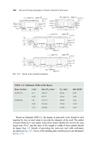
FIG. 5.47 Details of the retrofitted foundation.
TABLE 5.41 Minimum DCRs of the Braces
Brace Section L (m) Max (P UF ) (ton) P CL (ton) Min (DCR)
2UNP120 5.5 106.37 42.66 2.49
6.95 97.57 26.82 3.90
2UNP160 4.8 147.73 80.85 1.83
5.25 112.52 75.92 1.48
7.15 165.82 51.85 3.20
Based on Standard 2800 [2], the beams in jack-arch roofs should be tied
together by bars or steel strips to provide the integrity of the roof. The added
crossed elements in each panel tying these beams should not exceed the area
2
larger than 25m , and the ratio of the length to width of these panels should
be larger than 1.5. Details of providing the jack-arch roof with uniformity
are shown in Fig. 5.51. Views of the building after retrofit process are illustrated
in Fig. 5.52.