
Page 60 - Advanced Design Examples of Seismic Retrofit of Structures
P. 60
52 Advanced Design Examples of Seismic Retrofit of Structures
2.7.1 Demand Forces Calculations
Based on the LSP, the seismic demand force is calculated based on Section 3-3-
3-2 of Code 360 [10] as follows:
Q E ¼ C 1 C 2 C m S a W (2.1)
where:
Q E ¼pseudo lateral force;
S a ¼response spectrum acceleration, at the fundamental period and damp-
ing ratio of the building in the direction under consideration, which is deter-
mined based on Section 1–7 of Code 360 [10]. In this example, the
maximum response spectrum acceleration is considered based on the seismicity
of the site and also soil condition. This assumption is based on the fact that the
main target of this study is to propose a retrofit design for several masonry
school buildings of this type throughout Iran. Consequently, factors influencing
the fundamental period of structures including material properties, mass per unit
area of roof which can become significant from adding several insulation layers
over time and also using soils instead of porous aggregate (Fig. 2.32), slight
changes in openings size, etc.
W ¼effective seismic weight of the building, including the total dead load
and applicable codified portions of other gravity loads. According to Code 360,
the dead loads also include the weight of partition walls and the total operating
weight of permanent equipment, and the live loads are 20% of the codified live
loads including snow [10];
C 1 ¼modification factor to relate expected maximum inelastic displace-
ments to displacements calculated for linear elastic response. This factor is
determined based on either of these methods.
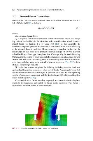
FIG. 2.32 The effects of OKB flexibility on the pier’s stiffness.