
Page 26 - Advanced Gas Turbine Cycles
P. 26
Chapter 1. A brief review of power genemtion thermodynamics 3
Control
surface
Reactants { ~ Combustion 1 ~Exhaust gases ~ ’ - ~ ~
I
chamber
(products)
Generator
IW
‘ Compressor Turbine I
1- - - - - - - - - - - - - -1
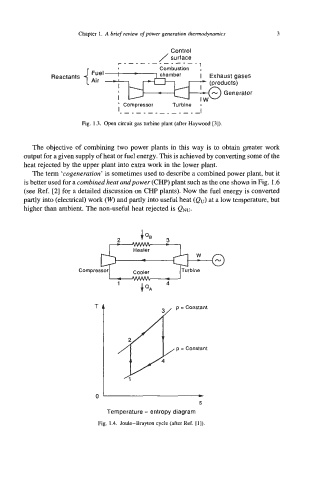
Fig. 1.3. Open circuit gas turbine plant (after Haywood [3]).
The objective of combining two power plants in this way is to obtain greater work
output for a given supply of heat or fuel energy. This is achieved by converting some of the
heat rejected by the upper plant into extra work in the lower plant.
The term ‘cogenerarion’ is sometimes used to describe a combined power plant, but it
is better used for a combined hear andpower (CHP) plant such as the one shown in Fig. 1.6
(see Ref. [2] for a detailed discussion on CHP plants). Now the fuel energy is converted
partly into (electrical) work (W) and partly into useful heat (eu) at a low temperature, but
higher than ambient. The non-useful heat rejected is Qw.
2
I -
Heater
Cooler Turbine
0’ rn
S
Temperature - entropy diagram
Fig. 1.4. Joule-Brayton cycle (after Ref. [I]).