
Page 102 - Advanced thermodynamics for engineers
P. 102
4.9 EXERGY 87
Temperature, T δT
(a) (b) 1h
2c
Control surface
T 1h T 2h
2h
T 2c T 1c
1c
4
T 0
3
6 5
Entropy, S
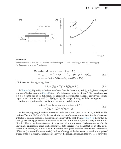
FIGURE 4.10
Reversible heat transfer in a counterflow heat exchanger. (a) Schematic diagram of heat exchanger;
(b) Processes shown on T–s diagram.
DB h ¼ B 2h B 1h ¼ðA 2h A 0 Þ ðA 1h A 0 Þ
¼ A 2h A 1h ¼ U þ p 0 V T 0 S U þ p 0 V T 0 S (4.53)
2h 1h
¼ U 2h U 1h T 0 S 2h S 1h þ p 0 V 2h V 1h
if it is assumed that V 1h ¼ V 2h , then
DB h ¼ðU 2h U 1h Þ T 0 ðS 2h S 1h Þ (4.54)
In Eqn (4.54), U 2h U 1h is the heat transferred from the hot stream, and S 2h S 1h is the change of
entropy of the hot stream. In Fig. 4.10, U 2h U 1h is the area 1h-2h-6-5-1h and T 0 (S 2h S 1h ) is the area
3-4-6-5-3. In the case of the hot stream, the change of energy and the change of entropy will both be
negative, and because (U 2h U 1h ) > T 0 (S 2h S 1h ) the change of exergy will also be negative.
A similar analysis can be done for the cold stream, and this gives
DB c ¼ B 2c B 1c ¼ðA 2c A 0 Þ ðA 1c A 0 Þ
(4.55)
¼ðU 2c U 1c Þ T 0 ðS 2c S 1c Þ
In this case, U 2c U 1c is the heat transferred to the cold stream (area 1c-2c-5-6-1c) and this will be
positive. The term T 0 (S 2c S 1c ) is the unavailable energy of the cold stream (area 4-3-5-6-4), and this
will also be positive because of the increase of entropy of the cold stream. Figure 4.10 shows that the
heating and cooling processes are effectively identical on the T–s diagram and only differ in their
direction. Hence, the change of energy of the hot and cold streams is equal (and opposite), and also the
unavailable energies are equal (and opposite) for both streams. This means that for an ideal coun-
terflow heat exchanger, in which the heat transfer takes place across an infinitesimal temperature
difference (i.e. reversible heat transfer) the loss of exergy of the hot stream is equal to the gain of
exergy of the cold stream. The change of exergy of the universe is zero, and the process is reversible.