Page 103 - Advanced thermodynamics for engineers
P. 103

88     CHAPTER 4 AVAILABILITY AND EXERGY


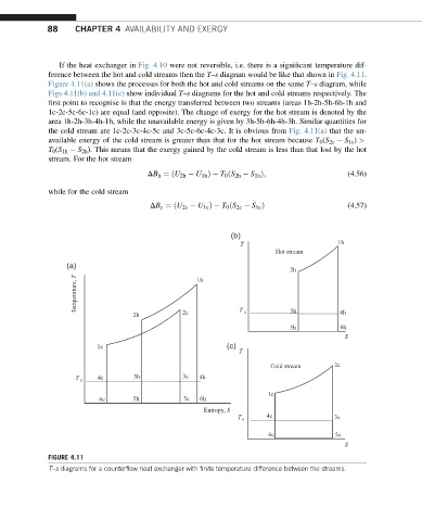
                If the heat exchanger in Fig. 4.10 were not reversible, i.e. there is a significant temperature dif-
             ference between the hot and cold streams then the T–s diagram would be like that shown in Fig. 4.11.
             Figure 4.11(a) shows the processes for both the hot and cold streams on the same T–s diagram, while
             Figs 4.11(b) and 4.11(c) show individual T–s diagrams for the hot and cold streams respectively. The
             first point to recognise is that the energy transferred between two streams (areas 1h-2h-5h-6h-1h and
             1c-2c-5c-6c-1c) are equal (and opposite). The change of exergy for the hot stream is denoted by the
             area 1h-2h-3h-4h-1h, while the unavailable energy is given by 3h-5h-6h-4h-3h. Similar quantities for
             the cold stream are 1c-2c-3c-4c-5c and 3c-5c-6c-4c-3c. It is obvious from Fig. 4.11(a) that the un-
             available energy of the cold stream is greater than that for the hot stream because T 0 (S 2c   S 1c ) >
             T 0 (S 1h   S 2h ). This means that the exergy gained by the cold stream is less than that lost by the hot
             stream. For the hot stream
                                       DB h ¼ðU 2h   U 1h Þ  T 0 ðS 2h   S 1h Þ;          (4.56)

             while for the cold stream

                                       DB c ¼ ðU 2c   U 1c Þ   T 0 ðS 2c   S 1c Þ         (4.57)


                                                            (b)
                                                              T                        1h
                                                                       Hot stream
                  (a)
                                                                           2h
                    Temperature, T
                                                   1h


                                   2h           2c            T  0         3h           4h
                                                                           5h           6h
                                                                                         S
                          1c                               (c)
                                                              T
                                                                      Cold stream     2c
                    T  0  4c       3h           3c  4h
                                                                     1c
                          6c       5h           5c  6h
                                                     Entropy, S
                                                              T  0   4c               3c

                                                                      6c               5c
                                                                                         S
             FIGURE 4.11
             T–s diagrams for a counterflow heat exchanger with finite temperature difference between the streams.
   98   99   100   101   102   103   104   105   106   107   108