Page 109 - Advanced thermodynamics for engineers
P. 109

94     CHAPTER 4 AVAILABILITY AND EXERGY


                   Assume that the specific heats for the gas are c p ¼ 1:005 kJ=kg K and c v ¼ 0:718 kJ=kg K:
                   [295.5 kJ; 509.6 kJ; 214.1 kJ]
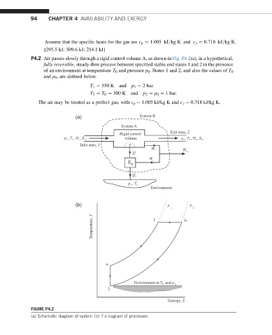
             P4.2 Air passes slowly through a rigid control volume A, as shown in Fig. P4.2(a), in a hypothetical,
                  fully reversible, steady-flow process between specified stable end states 1 and 2 in the presence
                  of an environment at temperature T 0 and pressure p 0 . States 1 and 2, and also the values of T 0
                  and p 0 , are defined below.

                                     T 1 ¼ 550 K  and  p 1 ¼ 2 bar:
                                     T 2 ¼ T 0 ¼ 300 K  and p 2 ¼ p 0 ¼ 1 bar:

                The air may be treated as a perfect gas, with c p ¼ 1.005 kJ/kg K and c v ¼ 0.718 kJ/kg K.

                               (a)                      System B

                                                 System A
                                                Rigid control        Exit state, 2
                          p , T , H , S ,            volume              p , T , H , S ,
                                 Inlet state, 1     T
                                                             W           W
                                                      Q
                                                            W
                                                    E R

                                                     Q
                                                    p  , T
                                                             Environment


                               (b)                                 p        p
                                                                     1       2
                                      Temperature, T          1           b


                                           a


                                                      Environment at T   and p 0
                                                                 0
                                            2
                                                                   Entropy, S
             FIGURE P4.2
             (a) Schematic diagram of system (b) T-s diagram of processes.
   104   105   106   107   108   109   110   111   112   113   114