
Page 34 - Advanced thermodynamics for engineers
P. 34
2.7 REPRESENTATION OF HEAT ENGINES 17
2.7 REPRESENTATION OF HEAT ENGINES
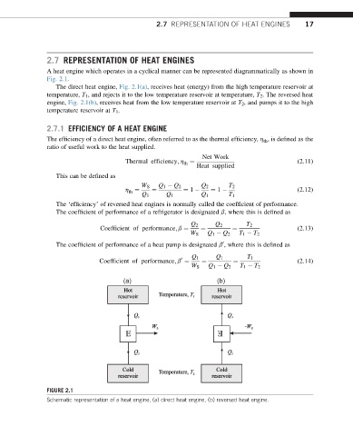
A heat engine which operates in a cyclical manner can be represented diagrammatically as shown in
Fig. 2.1.
The direct heat engine, Fig. 2.1(a), receives heat (energy) from the high temperature reservoir at
temperature, T 1 , and rejects it to the low temperature reservoir at temperature, T 2 . The reversed heat
engine, Fig. 2.1(b), receives heat from the low temperature reservoir at T 2 , and pumps it to the high
temperature reservoir at T 1 .
2.7.1 EFFICIENCY OF A HEAT ENGINE
The efficiency of a direct heat engine, often referred to as the thermal efficiency, h , is defined as the
th
ratio of useful work to the heat supplied.
Net Work
th
Thermal efficiency; h ¼ (2.11)
Heat supplied
This can be defined as
W S Q 1 Q 2 Q 2 T 2
h ¼ ¼ ¼ 1 ¼ 1 (2.12)
th
Q 1 Q 1 Q 1 T 1
The ‘efficiency’ of reversed heat engines is normally called the coefficient of performance.
The coefficient of performance of a refrigerator is designated b, where this is defined as
Q 2 Q 2 T 2
Coefficient of performance; b ¼ ¼ ¼ (2.13)
W S Q 1 Q 2 T 1 T 2
The coefficient of performance of a heat pump is designated b , where this is defined as
0
Q 1 Q 1 T 1
0 (2.14)
Coefficient of performance; b ¼ ¼ ¼
W S Q 1 Q 2 T 1 T 2
(a) (b)
FIGURE 2.1
Schematic representation of a heat engine, (a) direct heat engine, (b) reversed heat engine.