
Page 274 - Advanced Mine Ventilation
P. 274
Premining Degasification of Coal Seams 251
the drill head to the desired level. Two 5-in. telescopic hydraulic props, one on each
side, anchor the drill unit to the roof.
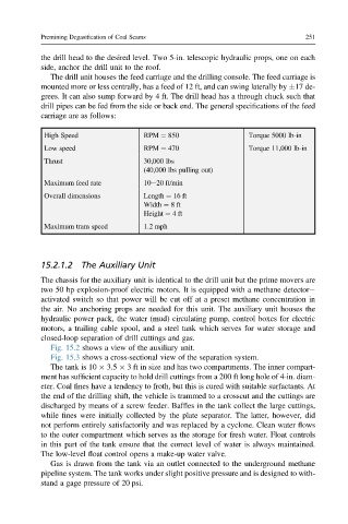
The drill unit houses the feed carriage and the drilling console. The feed carriage is
mounted more or less centrally, has a feed of 12 ft, and can swing laterally by 17 de-
grees. It can also sump forward by 4 ft. The drill head has a through chuck such that
drill pipes can be fed from the side or back end. The general specifications of the feed
carriage are as follows:
High Speed RPM ¼ 850 Torque 5000 lb-in
Low speed RPM ¼ 470 Torque 11,000 lb-in
Thrust 30,000 lbs
(40,000 lbs pulling out)
Maximum feed rate 10e20 ft/min
Overall dimensions Length ¼ 16 ft
Width ¼ 8ft
Height ¼ 4ft
Maximum tram speed 1.2 mph
15.2.1.2 The Auxiliary Unit
The chassis for the auxiliary unit is identical to the drill unit but the prime movers are
two 50 hp explosion-proof electric motors. It is equipped with a methane detectore
activated switch so that power will be cut off at a preset methane concentration in
the air. No anchoring props are needed for this unit. The auxiliary unit houses the
hydraulic power pack, the water (mud) circulating pump, control boxes for electric
motors, a trailing cable spool, and a steel tank which serves for water storage and
closed-loop separation of drill cuttings and gas.
Fig. 15.2 shows a view of the auxiliary unit.
Fig. 15.3 shows a cross-sectional view of the separation system.
The tank is 10 3.5 3 ft in size and has two compartments. The inner compart-
ment has sufficient capacity to hold drill cuttings from a 200 ft long hole of 4-in. diam-
eter. Coal fines have a tendency to froth, but this is cured with suitable surfactants. At
the end of the drilling shift, the vehicle is trammed to a crosscut and the cuttings are
discharged by means of a screw feeder. Baffles in the tank collect the large cuttings,
while fines were initially collected by the plate separator. The latter, however, did
not perform entirely satisfactorily and was replaced by a cyclone. Clean water flows
to the outer compartment which serves as the storage for fresh water. Float controls
in this part of the tank ensure that the correct level of water is always maintained.
The low-level float control opens a make-up water valve.
Gas is drawn from the tank via an outlet connected to the underground methane
pipeline system. The tank works under slight positive pressure and is designed to with-
stand a gage pressure of 20 psi.