
Page 276 - Advanced Mine Ventilation
P. 276
Premining Degasification of Coal Seams 253
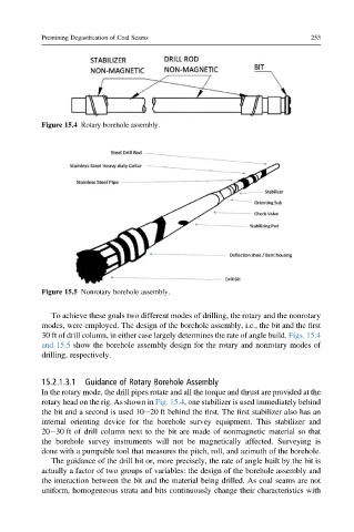
Figure 15.4 Rotary borehole assembly.
Figure 15.5 Nonrotary borehole assembly.
To achieve these goals two different modes of drilling, the rotary and the nonrotary
modes, were employed. The design of the borehole assembly, i.e., the bit and the first
30 ft of drill column, in either case largely determines the rate of angle build. Figs. 15.4
and 15.5 show the borehole assembly design for the rotary and nonrotary modes of
drilling, respectively.
15.2.1.3.1 Guidance of Rotary Borehole Assembly
In the rotary mode, the drill pipes rotate and all the torque and thrust are provided at the
rotary head on the rig. As shown in Fig. 15.4, one stabilizer is used immediately behind
the bit and a second is used 10e20 ft behind the first. The first stabilizer also has an
internal orienting device for the borehole survey equipment. This stabilizer and
20e30 ft of drill column next to the bit are made of nonmagnetic material so that
the borehole survey instruments will not be magnetically affected. Surveying is
done with a pumpable tool that measures the pitch, roll, and azimuth of the borehole.
The guidance of the drill bit or, more precisely, the rate of angle built by the bit is
actually a factor of two groups of variables: the design of the borehole assembly and
the interaction between the bit and the material being drilled. As coal seams are not
uniform, homogeneous strata and bits continuously change their characteristics with