
Page 324 - Advanced Mine Ventilation
P. 324
Gas Transport in Underground Coal Mines 301
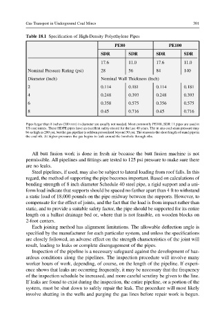
Table 18.1 Specification of High-Density Polyethylene Pipes
PE80 PE100
SDR SDR SDR SDR
17.6 11.0 17.6 11.0
Nominal Pressure Rating (psi) 28 56 84 140
Diameter (Inch) Nominal Wall Thickness (Inch)
2 0.114 0.181 0.114 0.181
4 0.248 0.393 0.248 0.393
6 0.358 0.575 0.356 0.575
8 0.45 0.716 0.45 0.716
Pipes larger than 8 inches (200 mm) in diameter are usually not needed. Most commonly PE100, SDR 11 pipes are used in
US coal mines. These HDPE pipes have an excellent safety record for the last 40 years. The in situ coal seam pressure may
be as high as 200 psi, but the gas pipeline is seldom pressurized beyond 50 psi. The reason is the short length of stand pipe in
the coal rib. At higher pressures the gas begins to leak around the borehole through ribs.
All butt fusion work is done in fresh air because the butt fusion machine is not
permissible. All pipelines and fittings are tested to 125 psi pressure to make sure there
are no leaks.
Steel pipelines, if used, may also be subject to lateral loading from roof falls. In this
regard, the method of supporting the pipe becomes important. Based on calculations of
bending strength of 8 inch diameter Schedule 40 steel pipe, a rigid support and a uni-
form load indicate that supports should be spaced no farther apart than 4 ft to withstand
a static load of 18,000 pounds on the pipe midway between the supports. However, to
compensate for the effect of joints, and the fact that the load is from impact rather than
static, and to provide a suitable safety factor, the pipe should be supported for its entire
length on a ballast drainage bed or, where that is not feasible, on wooden blocks on
2-foot centers.
Each joining method has alignment limitations. The allowable deflection angle is
specified by the manufacturer for each particular system, and unless the specifications
are closely followed, an adverse effect on the strength characteristics of the joint will
result, leading to leaks or complete disengagement of the pipes.
Inspection of the pipeline is a necessary safeguard against the development of haz-
ardous conditions along the pipelines. The inspection procedure will involve many
worker hours of work, depending, of course, on the length of the pipeline. If experi-
ence shows that leaks are occurring frequently, it may be necessary that the frequency
of the inspection schedule be increased, and more careful scrutiny be given to the line.
If leaks are found to exist during the inspection, the entire pipeline, or a portion of the
system, must be shut down to safely repair the leak. The procedure will most likely
involve shutting in the wells and purging the gas lines before repair work is begun.