
Page 74 - Advanced Mine Ventilation
P. 74
Estimation of Ventilation Air Quantity 57
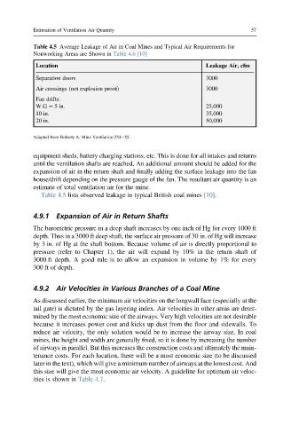
Table 4.5 Average Leakage of Air in Coal Mines and Typical Air Requirements for
Nonworking Areas are Shown in Table 4.6 [10]
Location Leakage Air, cfm
Separation doors 3000
Air crossings (not explosion proof) 3000
Fan drifts:
W.G ¼ 5 in. 25,000
10 in. 35,000
20 in. 50,000
Adapted from Roberts A. Mine Ventilation:254e55.
equipment sheds, battery charging stations, etc. This is done for all intakes and returns
until the ventilation shafts are reached. An additional amount should be added for the
expansion of air in the return shaft and finally adding the surface leakage into the fan
house/drift depending on the pressure gauge of the fan. The resultant air quantity is an
estimate of total ventilation air for the mine.
Table 4.5 lists observed leakage in typical British coal mines [10].
4.9.1 Expansion of Air in Return Shafts
The barometric pressure in a deep shaft increases by one inch of Hg for every 1000 ft
depth. Thus in a 3000 ft deep shaft, the surface air pressure of 30 in. of Hg will increase
by 3 in. of Hg at the shaft bottom. Because volume of air is directly proportional to
pressure (refer to Chapter 1), the air will expand by 10% in the return shaft of
3000 ft depth. A good rule is to allow an expansion in volume by 1% for every
300 ft of depth.
4.9.2 Air Velocities in Various Branches of a Coal Mine
As discussed earlier, the minimum air velocities on the longwall face (especially at the
tail gate) is dictated by the gas layering index. Air velocities in other areas are deter-
mined by the most economic size of the airways. Very high velocities are not desirable
because it increases power cost and kicks up dust from the floor and sidewalls. To
reduce air velocity, the only solution would be to increase the airway size. In coal
mines, the height and width are generally fixed, so it is done by increasing the number
of airways in parallel. But this increases the construction costs and ultimately the main-
tenance costs. For each location, there will be a most economic size (to be discussed
later in the text), which will give a minimum number of airways at the lowest cost. And
this size will give the most economic air velocity. A guideline for optimum air veloc-
ities is shown in Table 4.7.