
Page 175 - Advances in Forensic Applications of Mass Spectrometry - Jehuda Yinon
P. 175
1522_C04.fm Page 158 Thursday, November 13, 2003 9:54 AM
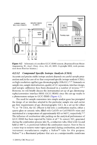
Figure 4.2 Schematic of a modern GC/C-IRMS system. (Reprinted from Meier-
Augenstein, W., Anal. Chim. Acta, 465, 63, 2002. Copyright 2002, with permis-
sion from Elsevier Science.)
4.2.3.2 Compound Specific Isotope Analysis (CSIA)
Accurate and precise stable isotope analysis depends on careful sample prep-
aration and, in the case of on-line compound specific isotope analysis (CSIA),
on high-resolution capillary gas chromatography (HRcGC). 16,27 Demands on
sample size, sample derivatization, quality of GC separation, interface design,
and isotopic calibration have been discussed in a number of reviews. 11,28-31
However, we will briefly discuss the instrumental set-up of gas chromatog-
raphy/conversion interface-IRMS (GC/C-IRMS) since this set-up results in
a phenomenon unique to GC/C-IRMS (Figure 4.2).
The need for sample conversion into simple analyte gases has prompted
the design of an interface adapted to the particular sample size and carrier
gas flow requirements of gas chromatography (GC). In a set-up for either
15
13 C or N CSIA, the GC effluent is fed into a combustion reactor, either a
quartz glass or ceramic tube, filled with CuO/Pt or CuO/NiO/Pt wires and
maintained at a temperature of approximately 820 or 940˚C, respectively. 32,33
The influence of combustion tube packing on the analytical performance of
34
GC/C-IRMS has been reported by Eakin et al. To convert NO generated
x
during the combustion process into N , a reduction tube, filled with Cu and
2
held at 600 ˚C, is positioned behind the combustion reactor. Next in line is
a water trap to remove water vapor generated during combustion, and most
instrument manufacturers employ a Nafion TM tube for this purpose.
Nafion TM is a fluorinated polymer that acts as a semipermeable membrane
© 2004 by CRC Press LLC