
Page 201 - Advances in Forensic Applications of Mass Spectrometry - Jehuda Yinon
P. 201
1522_book.fm Page 184 Thursday, November 13, 2003 9:58 AM
This chapter will describe the operation of an ion trap for MS/MS
analysis of fire debris evidence. The ion trap can store ions for subsequent
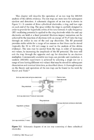
ejection and detection. A schematic diagram of an ion trap is shown in
Figure 5.1. It consists of three cylindrical electrodes, a ring, and two caps
on each end of the ring. The space within the rings is carefully designed in
order to provide for hyperbolic orbits of the ions formed. A radio frequency
(RF) oscillating potential is applied to the ring electrode while the end cap
electrodes are held at a fixed potential. Electron impact ionization can be
achieved by the injection of electrons with an energy of 70 eV into the trap
through an orifice in one of the end cap electrodes. The RF potential
provides stable orbits for a range of ion masses so that these can be stored
(typically the 30 to 450 m/z range is used in the analysis of fire debris
evidence). The ions may be ejected from the trap, in order of increasing
m/z values, by increasing the amplitude of the RF potential. The ions will
exit the trap through the opposite end cap for detection by an electron
multiplier. Commercially available ion traps can provide unit resolution. A
tandem (MS/MS) experiment is achieved by selecting a single ion (or a
range of ions having different m/z values) that may be stored for subsequent
dissociation and eventual detection, as described above. A thorough treatise
on the theory and operation of the ion trap can be found in the work by
March and Todd. 16
End cap electrode (entrance electrode) Electron lens
Gate electrode
Ring electrode
End cap electrode (7 hole exit electrode)
Ring electrode
End cap electrode (entrance electrode)
Hyperbolic surfaces
End cap electrode (7 holes)
Figure 5.1 Schematic diagram of an ion trap consisting of three cylindrical
electrodes.
© 2004 by CRC Press LLC