
Page 208 - Advances in Renewable Energies and Power Technologies
P. 208
3. Necessity of Joint Adoption of Distributed Maximum Power Point 181
More precisely, rather than the whole approximate characteristic of all the
LSCPVUs belonging to a given string, what is needed by the FEMPV algorithm
is the knowledge of the position of a few key points on such a characteristic. This
subsection is also devoted to the identification of the guidelines to follow to obtain
the approximate version of the IeV characteristic of a given LSCPVU. In particular,
subsection “Boost-based LSCPVUs” is devoted to boost-based LSCPVUs, subsec-
tion “BuckeBoost based LSCPVUs” to buckeboost based LSCPVUs, and finally,
subsection “Buck-based LSCPVUs” to buck-based LSCPVUs. In subsections
“Boost-based LSCPVUs”, “BuckeBoost based LSCPVUs” and “Buck-based
LSCPVUs”, V will represent the output voltage and I the output current of an
LSCPVU.
3.2.1.1 Boost-Based Lossless Self Controlled Photovoltaic Units
As discussed in detail in [61], the exact IeV and PeV characteristics of a boost-
based LSCPVU can be subdivided into three portions. In particular, for
0 V V MPP , the corresponding portions of the IeV and PeV characteristics of
the LSCPVU are, respectively, coincident, with the IeV and PeV characteristics
of the adopted PV module in the considered atmospheric conditions (irradiance
value and ambient temperature) [54,55]. Instead, for V MPP V < V ds max , the cor-
responding portions of IeV and PeV characteristics of the LSCPVU are, respec-
tively, a hyperbole of Eq. I ¼ P MPP /V and a straight line of equation P ¼ P MPP ,
where P MPP is the maximum power that can be provided by the adopted PV module
in the considered atmospheric conditions [54,55]. The third portion of the IeV and
PeV characteristics are represented by a vertical drop located at V ¼ V ds max and
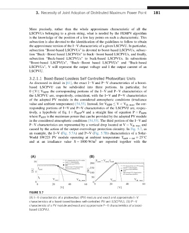
caused by the action of the output overvoltage protection circuitry. In Fig. 5.7,as
an example, the IeV(Fig. 5.7A) and PeV(Fig. 5.7B) characteristics of a Solar-
World SW225 PV module operating at ambient temperature T amb ¼ ent ¼ 25 C
and at an irradiance value S ¼ 1000 W/m 2 are reported together with the
(A) (B)
I-V characteristic of a PV module P = V ∙I
10 exact I-V characteristic cost cost cost
of a boost based SCPVC 200
MPP P-V characteristic of a PV module
approximate I-V characteristic
I cost of a boost based SCPVU exact P-V characteristic
[A] 5 [W] 150 of a boost based SCPVU
MPP
100
approximate P-V characteristic
of a boost based SCPVU
I 0 50
V cost V ds_max V cost V ds_max
0 0
0 20 40 60 0 20 40 60
[V] [V]
FIGURE 5.7
(A) IeV characteristic of a photovoltaic (PV) module and exact and approximate IeV
characteristics of a boost-based lossless self-controlled PV unit (LSCPVU), (B) PeV
characteristic of a PV module and exact and approximate PeV characteristics of a boost-
based LSCPVU.