
Page 211 - Advances in Renewable Energies and Power Technologies
P. 211
184 CHAPTER 5 DMPPT PV System: Modeling and Control Techniques
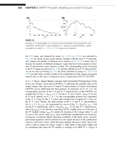
FIGURE 5.8
(A) Exact IeV characteristic of 11 series-connected lossless self-controlled PV units
(LSCPVUs). (B) Exact PeV characteristics of 11 series-connected LSCPVUs, points
calculated by using Eqs. (5.23) and (5.24) (grey circle markers).
the IeV plane, and obtained by using Eqs. (5.23) and (5.24), are indicated in
Fig. 5.8A by means of grey circle markers, together with the exact IeV character-
istic. Indeed, the number of different circle markers in Fig. 5.8A is lower than 33
because the number of different irradiance values that have been assumed is lower
than N and therefore some markers overlap. The corresponding points belonging
to the PeV plane are shown in Fig. 5.8B together with the exact PeV characteristic.
As can be seen by looking Fig. 5.8, the points obtained by using Eqs. (5.23) and
(5.24) provide fairly accurate results in the neighborhood of R b (region of greatest
interest) that, in this case, is characterized by a single point (251.9 V, 767.9 W).
3.2.1.2 BuckeBoost Based Lossless Self-Controlled Photovoltaic Units
In the case of buckeboost based LSCPVUs, V represents the absolute value of the
output voltage. Also, the exact IeVand PeV characteristics of a buckeboost based
LSCPVU can be subdivided into three portions. In particular, for 0 V V 1 , the
corresponding portions of the IeV and PeV characteristics of the LSCPVU are
straight lines of Eq. I ¼ I MAX [54,55] for the IeV curve and P ¼ I MAX ,V for the
PeV curve. Instead, for V 1 V V 2 , the corresponding portions are a hyperbole
of Eq. V$I ¼ P MPP for the IeV curve and a straight line of equation P ¼ P MPP for
the PeV curve. Finally, the third portion of the IeV and PeV characteristics,
for V 2 V V ds max , are represented by curves of Eq. V ¼ P pan (V ds max e V)/I
for the IeV characteristic and P ¼ P pan (V ds max e V) for the PeV characteristic,
where P pan (v pan ) is the function expressing the PV module power as a function of
the PV module voltage v pan . To explain the meaning of the voltage values V 1 and
V 2 and of the current value I MAX , some preliminary considerations are necessary.
Continuous Conduction Mode operating conditions of the buckeboost converter
and related equations will be referred to in the sequel, because of the synchronous
version of the buckeboost, which has been adopted. Because a buckeboost con-
verter is able to reduce its output voltage V with respect to the input voltage and
by considering that when the PV module is working in its MPP (V$I ¼ P MPP ), it