Page 215 - Advances in Renewable Energies and Power Technologies
P. 215

188    CHAPTER 5 DMPPT PV System: Modeling and Control Techniques


                         point moves away from the MPP because the output power becomes lower than
                         P MPP . By indicating with D the duty-cycle of the buck converter, when the PV mod-
                         ule operates in the MPP, it is [53]:

                                                    V MPP $I MPP  I MPP
                                                 I ¼          ¼
                                                        V        D
                                                                                       (5.36)
                                                         I MPP
                                                 I s peak ¼
                                                          D
                         where I s peak , is the peak current value of the switches of the buck. From Eq. (5.36) it
                         is evident that, while the PV module operating point remains in the MPP, the lower D
                         (and hence the lower V) the higher both the output current and the peak current of
                         the switches. By indicating with D 1 the value of D in correspondence of which the
                         peak current of the switches is equal to I ds max and therefore the output current also
                         assumes its maximum allowed value I MAX and by considering Eq. (5.36) we get:
                                                                                       (5.37)
                                                    I MAX ¼ I ds max
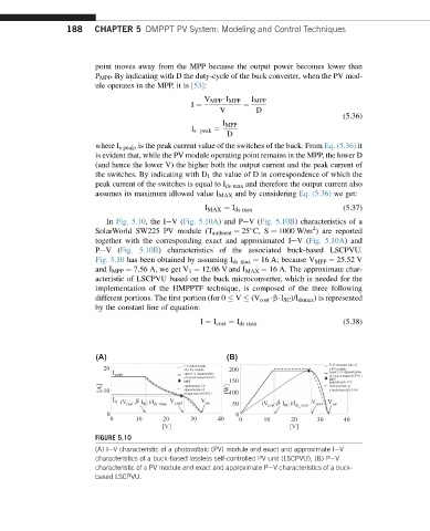
                            In Fig. 5.10, the IeV(Fig. 5.10A) and PeV(Fig. 5.10B) characteristics of a
                                                                               2

                         SolarWorld SW225 PV module (T ambient ¼ 25 C, S ¼ 1000 W/m ) are reported
                         together with the corresponding exact and approximated IeV(Fig. 5.10A) and
                         PeV(Fig. 5.10B) characteristics of the associated buck-based LSCPVU.
                         Fig. 5.10 has been obtained by assuming I ds max ¼ 16 A; because V MPP ¼ 25.52 V
                         and I MPP ¼ 7.56 A, we get V 1 ¼ 12.06 V and I MAX ¼ 16 A. The approximate char-
                         acteristic of LSCPVU based on the buck microconverter, which is needed for the
                         implementation of the HMPPTF technique, is composed of the three following
                         different portions. The first portion (for 0   V   (V cost $b$I SC )/I dsmax ) is represented
                         by the constant line of equation:
                                                   I ¼ I cost ¼ I ds max               (5.38)


                         (A)                              (B)
                                                                                    P-V characteristic of
                                               I-V characteristic
                           20                  of a PV module  200                  a PV module
                             I cost            exact I-V characteristic             exact P-V characteristic
                                               of a buck based SCPVU                of a buck based SCPVU
                                                                                    MPP
                                               MPP        150                       approximate P-V
                          [A]  10              approximate I-V  [W]                 characteristic of
                                               characteristic of
                                                                                    a buck based SCPVU
                                               a buck based SCPVU  100
                             I              V      V
                              0 (V cost  .β.  I SC )/I ds_max  cost  oc  50  (V cost  .β .  I SC )/I ds_max  V cost V oc
                            0                               0
                             0     10     20     30     40   0     10     20    30     40
                                          [V]                             [V]
                         FIGURE 5.10
                         (A) IeV characteristic of a photovoltaic (PV) module and exact and approximate IeV
                         characteristics of a buck-based lossless self-controlled PV unit (LSCPVU), (B) PeV
                         characteristic of a PV module and exact and approximate PeV characteristics of a buck-
                         based LSCPVU.
   210   211   212   213   214   215   216   217   218   219   220