
Page 220 - Advances in Renewable Energies and Power Technologies
P. 220
3. Necessity of Joint Adoption of Distributed Maximum Power Point 193
FIGURE 5.13
Exact IeV characteristics lossless self-controlled photovoltaic units (LSCPVUs). Grey
square markers indicate maximum power points.
the case of the following set of operating conditions and parameters: S ¼ [1000,
2
1000, 1000, 1000, 1000, 1000, 1000, 1000, 1000, 500, 500] W/m ;
Tambient ¼ 25 C; V ds max ¼ 60 V. By assuming that the allowed inverter DC input
voltage range is equal to [350, 600] V, the FEMPV-based analysis provides the
following value: V h ¼ 556.6 V; while the exact analysis provides V h ¼ 564.55 V.
Therefore, we assume that the operating inverter voltage will initially be
V h ¼ 556.6 V and, after the hill climbing refinement process, will be
V h ¼ 564.55 V. In correspondence of such a voltage value, from the IeVexact char-
acteristic it is I h ¼ 3.493 A. As shown in Fig. 5.13, the intersections among the hor-
izontal dashed lines representing I h ¼ 3.493 A with the IeV output exact
characteristics of the various LSCPVUs are found in the hyperbolic portions of
the IeV characteristics of all the LSCPVUs. Therefore, in the considered case,
the PV modules of all the LSCPVUs will operate in their MPPs.
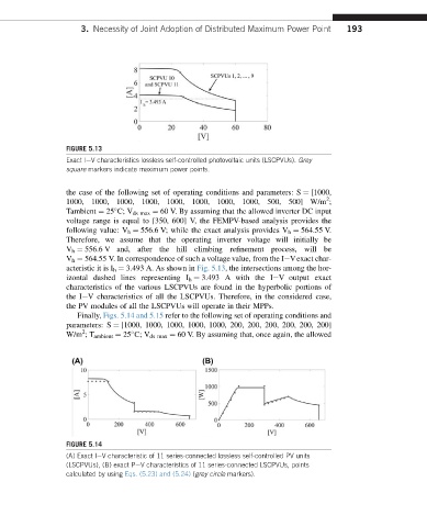
Finally, Figs. 5.14 and 5.15 refer to the following set of operating conditions and
parameters: S ¼ [1000, 1000, 1000, 1000, 1000, 200, 200, 200, 200, 200, 200]
2
W/m ;T ambient ¼ 25 C; V ds max ¼ 60 V. By assuming that, once again, the allowed
FIGURE 5.14
(A) Exact IeV characteristic of 11 series-connected lossless self-controlled PV units
(LSCPVUs), (B) exact PeV characteristics of 11 series-connected LSCPVUs, points
calculated by using Eqs. (5.23) and (5.24) (grey circle markers).