
Page 225 - Advances in Renewable Energies and Power Technologies
P. 225
198 CHAPTER 5 DMPPT PV System: Modeling and Control Techniques
the value adopted in HMPPTF technique). The advantages associated with the adop-
tion of a higher value of V out lim are clearly evident in Fig. 5.17A. For the sake of
completeness, in Fig. 5.17B, both the exact and the approximate PeV characteristics
obtained by assuming V out lim ¼ 59 V are reported. It is worth remembering that,
while the approximate characteristic is used by the FEMPV algorithm, the exact
characteristic must be considered if one is interested in the accurate verification
of the actual power extracted from the PV system. The values of the remaining
parameters adopted in HMPPTF technique are: Dt ¼ 1s, V cost ¼ 26.24 V. The
remaining parameters adopted in HMPPTS technique have been chosen on the
basis of the guidelines provided by Eqs. (5.13) and (5.15) for the value of
Dv b ref and by Eqs. (5.17) and (5.19) for the value of T b . By assuming
P ¼N$V MPP $I PMM ¼ 2475 W, f line ¼ 50 Hz, V a ¼ V inverter_min ¼ 360 V, and
C b ¼ 1 mF and by applying Eqs. (5.13) and (5.15), the allowed range of Dv b ref
can be obtained:
21:9V Dv b ref 47:55 V (5.47)
On the basis of the above considerations, Dv b ref has been chosen to be equal to
25 V. As concerns the value of T b , it must fulfill the following inequalities:
T b T tot ¼ 0:75 s (5.48)
In this case, T b has been chosen to be equal to 1 s. More details regarding the
calculation of T tot are reported in [62].
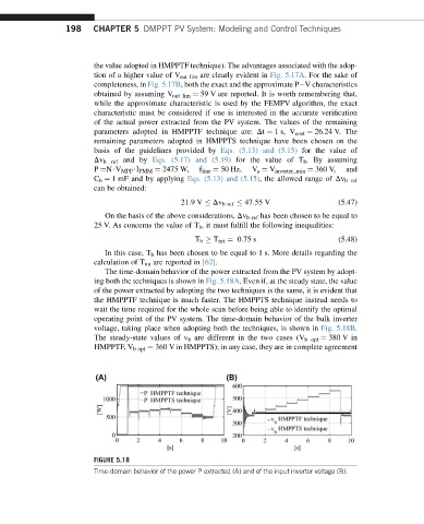
The time-domain behavior of the power extracted from the PV system by adopt-
ing both the techniques is shown in Fig. 5.18A. Even if, at the steady state, the value
of the power extracted by adopting the two techniques is the same, it is evident that
the HMPPTF technique is much faster. The HMPPTS technique instead needs to
wait the time required for the whole scan before being able to identify the optimal
operating point of the PV system. The time-domain behavior of the bulk inverter
voltage, taking place when adopting both the techniques, is shown in Fig. 5.18B.
The steady-state values of v b are different in the two cases (V b opt ¼ 380 V in
HMPPTF, V b opt ¼ 360 V in HMPPTS); in any case, they are in complete agreement
FIGURE 5.18
Time-domain behavior of the power P extracted (A) and of the input inverter voltage (B).