
Page 226 - Advances in Renewable Energies and Power Technologies
P. 226
3. Necessity of Joint Adoption of Distributed Maximum Power Point 199
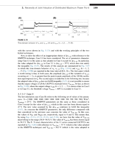
FIGURE 5.19
Time-domain behavior of v b and v b ref (A) and v outk (k ¼ 1,2, .,7) (B).
with the curves shown in Fig. 5.17A and with the working principles of the two
hybrid techniques.
Now, to show the effect of an inappropriate choice of Dv bref with reference to the
HMPPTS technique, Case I.1 has been considered. The set of parameters character-
izing Case I.1 is the same as that adopted in Case I except for Dv bref. In particular,
the value adopted for Dv bref in Case I.1 is Dv bref ¼ 55 V, which does not satisfy
the inequality Eq. (5.47). The results of this analysis are summarized in Fig. 5.19
in which the time-domain behavior of v b ,v bref (Fig. 5.19A)and v outk (k ¼ 1, 2,
.,7) (Fig. 5.19B) are reported in the time interval [0.4, 2] s. The first aspect which
is worth noting is that, in both cases, the amplitude Dv bref of the variation of v bref ,
occurring at t ¼ 1 s, is greater than the peak-to-peak amplitude of the 100 Hz oscilla-
tion superimposed on v b . The second aspect to underline is the following one; because
the adopted value of Dv bref does not fulfill inequality (5.47), it is not possible to ensure
that the output voltages of all the LSCPVUs maintain below V ds max . In fact, as shown
in Fig. 5.19B, where the output voltage v outk (k ¼ 1, 2, ., 7) is shown either in Case I
or in Case I.1, the threshold voltage V dsmax ¼ 60V is exceeded in Case I.1.
3.2.3.2 Case II
The last simulation case (Case II) refers to the following set of values of the param-
2
eters: S ¼ [1000 1000 1000 1000 1000 1000 1000 390 390 390 390] W/m ,
T ambient ¼ 25 C. The HMPPTS parameters are the same as those considered in
Case I except for the value of Dv b ref , which in this case has been chosen equal to
47 V. The new value assumed by the Dv b ref continues to fulfill the inequality
(5.47). As concerns the HMPPTF parameters, the only difference compared with
that considered in the previous case concerns the value of V out lim . In this case,
the values of N SC and N MPP are, respectively, equal to 0 and 4. This means that,
by using Eqs. (5.11), (5.12), (5.44), and (5.46), we have that the value of V out lim
must belong to the range [36.8e58.5] V. The value of V out lim has been chosen equal
to 58.5 V. The PeV exact characteristics of the 11 series-connected LSCPVUs are
reported in Fig. 5.20A with reference to V out lim ¼ 53 V (which is the value adopted
in the HMPPTS technique) and V out lim ¼ 58.5 V (which is the value adopted in