
Page 219 - Advances in Renewable Energies and Power Technologies
P. 219
192 CHAPTER 5 DMPPT PV System: Modeling and Control Techniques
LSCPVUs 1 and 2 will operate at the maximum allowed output voltage. In the case
of LSCPVUs 3 and 4, the intersection is found in the hyperbolic portion of the IeV
characteristic; therefore, the PV modules of LSCPVUs 3 and 4 will operate in their
MPPs. In the case of LSCPVUs 5 and 6, the intersection takes place at a voltage
slightly lower than the MPP voltage, as it is clearly shown in Fig. 5.11 where the
grey square markers just indicate the position of the MPPs; therefore, the PV mod-
ules of LSCPVUs 3 and 4 will operate at a voltage slightly lower than their MPP
voltage. Finally, LSCPVUs 7, 8, 9, 10, and 11 will operate in short circuit conditions
because I h is higher than the short circuit currents of their associated PV modules.
In the above case, a voltage nearly equal to 251 V represents the best inverter
input operating voltage. But, if the allowed inverter DC input voltage range is, for
example, equal to [350, 600] V, then the FEMPV algorithm is of course able to pro-
vide the best operating voltage value V h included in such a range. In the considered
case, it is V h ¼398.3 V [see Fig. 5.8B), the exact and the approximate optimal values
in the range [350, 600] Vare nearly coincident]. In correspondence of V h ¼ 398.3 V,
from the IeV output exact characteristic of the string of LSCPVUs it is possible to
get I h ¼ 1.53 A. By considering the location, in Fig. 5.11, of the intersections among
the horizontal dashed line representing I h ¼ 1.53 A with the IeVoutput exact char-
acteristics of the various LSCPVUs it is possible to draw the following conclusions.
In correspondence of a DC inverter input voltage V h ¼ 398.3 Vand hence I h ¼ 1.53
A, in the case of LSCPVUs 1, 2, 3, and 4, such an intersection is found in the vertical
portion of the IeV characteristics, at V ¼ V ds max . Therefore, LSCPVUs 1, 2, 3, and
4 will operate at the maximum allowed output voltage. In the case of LSCPVUs 5
and 6, the intersection is found in the hyperbolic portion of the IeV characteristic;
therefore, the PV modules of LSCPVUs 5 and 6 will operate in their MPPs. In the
case of LSCPVUs 7 and 8, the intersection takes place at a voltage slightly lower
than the MPP voltage; therefore, the PV modules of LSCPVUs 7 and 8 will operate
at a voltage slightly lower than their MPP voltage. Finally, LSCPVUs 9, 10, and 11
will operate in short circuit conditions because I h ¼ 1.53 A is higher than the short
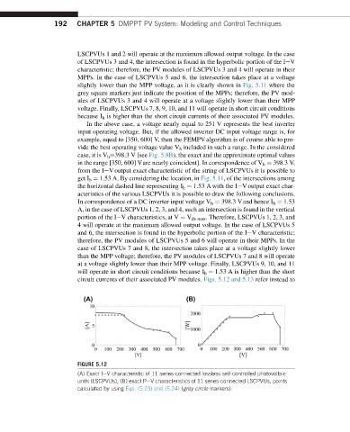
circuit currents of their associated PV modules. Figs. 5.12 and 5.13 refer instead to
FIGURE 5.12
(A) Exact IeV characteristic of 11 series-connected lossless self-controlled photovoltaic
units (LSCPVUs), (B) exact PeV characteristics of 11 series-connected LSCPVUs, points
calculated by using Eqs. (5.23) and (5.24) (grey circle markers).