
Page 214 - Advances in Renewable Energies and Power Technologies
P. 214
3. Necessity of Joint Adoption of Distributed Maximum Power Point 187
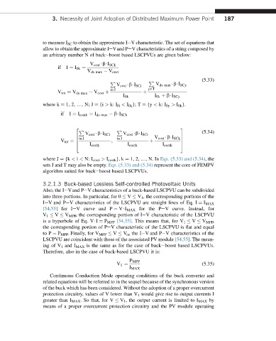
to measure I SC to obtain the approximate IeV characteristic. The set of equations that
allow to obtain the approximate IeVand PeV characteristics of a string composed by
an arbitrary number N of buckeboost based LSCPVUs are given below:
V cost $b$I SCk
if I ¼ I 0k ¼
V ds max V cost
(5.33)
P
P
V cost $b$I SCi V ds max $b$I SCy
i˛J y˛T
V tot ¼ V ds max V cost þ þ
I 0k I 0k þ b$I SCy
where k ¼ 1, 2, .,N;J ¼ {i > k: I 0i < I 0k }; T ¼ {y < k: I 0y > I 0k }.
if I ¼ I costk ¼ I ds max b$I SCk
2 3
(5.34)
P P
V cost $b$I SCi V cost $b$I SCi
6 i˛J i˛J V cost $b$I SCk 7
V tot ¼ 6 ; þ 7
I costk I costk I costk
4 5
where J ¼ {k < i < N: I costi > I costk }, k ¼ 1, 2, .,N. In Eqs. (5.33) and (5.34), the
sets J and T may also be empty. Eqs. (5.33) and (5.34) represent the core of FEMPV
algorithm suited for buckeboost based LSCPVUs.
3.2.1.3 Buck-based Lossless Self-controlled Photovoltaic Units
Also, the IeVand PeV characteristics of a buck-based LSCPVU can be subdivided
into three portions. In particular, for 0 V V 1 , the corresponding portions of the
IeV and PeV characteristics of the LSCPVU are straight lines of Eq. I ¼ I MAX
[54,55] for IeV curve and P ¼ V$I MAX for the PeV curve. Instead, for
V 1 V V MPP , the corresponding portion of IeV characteristic of the LSCPVU
is a hyperbole of Eq. V$I ¼ P MPP [54,55]. This means that, for V 1 V V MPP ,
the corresponding portion of PeV characteristic of the LSCPVU is flat and equal
to P ¼ P MPP . Finally, for V MPP V V oc the IeV and PeV characteristics of the
LSCPVU are coincident with those of the associated PV module [54,55]. The mean-
ing of V 1 and I MAX is the same as for the case of buckeboost based LSCPVUs.
Therefore, also in the case of buck-based LSCPVU it is:
P MPP
V 1 ¼ (5.35)
I MAX
Continuous Conduction Mode operating conditions of the buck converter and
related equations will be referred to in the sequel because of the synchronous version
of the buck which has been considered. Without the adoption of a proper overcurrent
protection circuitry, values of V lower than V 1 would give rise to output currents I
greater than I MAX . So that, for V V 1 , the output current is limited to I MAX by
means of a proper overcurrent protection circuitry and the PV module operating