
Page 62 - Advances in Renewable Energies and Power Technologies
P. 62
5. The PV Arrays 35
+
RI
–15V 2.2Ω
IREP260N
1 PV
Module
DAQ 3 + 5 +
LM741 RV
RIN 2 – Voltage 10Ω
10Ω acquiring
4
–
–15V
Rf RI –
10Ω
0.07Ω
Current
acquiring
+ –
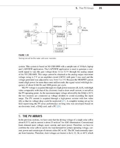
FIGURE 1.30
Testing circuit for the solar cells and modules.
system. This system is based on NI-USB 6008 with a sample rate of 10 Ks/s, laptop
and LABVIEW application. The LAPVIEW application is used to generate a saw-
tooth signal to vary the gate voltage from 3.4 to 5.5 V through the analog output
of the NI-USB 6008. This range cannot be obtained as the analog output maximum
voltage swing is 5 V so an amplifier circuit LM741 with gain 2 was used and the
voltage generated was adjusted to vary from 1 to 3 V. Because the MOSFET cannot
stand a high power for more than some milliseconds, the signal varied with high fre-
quency of about 0.166 Hz and 1000 points per cycle.
The PV voltage is acquired through two high-power resistors (R 1 & R v ) with high
value comparable with that of the electronic load to draw small current, to not affect
the PVoperating point. As the maximum input voltage allowed by the DAQ is 10 V,
the two resistors are connected as voltage dividers to avoid exceeding the input
range. The PV current is acquired through a high-power resistor with low value
(R I ) so that its voltage drop could be neglected [27]. A complete testing set up for
field supervising the PV array performance on long time was developed based on
an electronic load, a DAQ card, and a PC [28].
5. THE PV ARRAYS
In the previous sections, we have seen that the driving voltage of a single solar cell is
2
about 0.55 V, and its current is about 35 mA/cm for AM1 illumination. Conventional
loads demand more voltage, more current, and more power. Therefore, we have to
combine the solar cells to satisfy the load demand for certain operating voltage, cur-
rent, power and certain type of current; either DC or AC. The DC loads normally oper-
ate from batteries. Therefore, their voltages are known to be 6, 12, 24, or 48 V, which