
Page 152 - Aerodynamics for Engineering Students
P. 152
Potential flow 135
On integrating from 0 to 27r the first and third terms vanish leaving
1" 4B sin2 0 d0 = 4B7r
Therefore
1
1 = -pU2a4B7r
2
Replacing B by I'/27rUa and cancelling gives the equation for the lift force per unit
span
I = pur (3.52)
The lift per unit span in N is equal to the product of density p, the linear velocity U,
and the circulation r.
This expression is the algebraic form of the Kutta-Zhukovsky theorem, and is
valid for any system that produces a circulation superimposed on a linear velocity
(see Section 4.1.3). The spinning cylinder is used here as it lends itself to stream
function theory as well as being of interest later.
It is important to note that the diameter of the cylinder has no influence on the
final expression, so if a line vortex of strength r moved with velocity U in a uniform
flow of density p, the same sideways force 1 = pur per unit length of vortex would be
found. This sideways force commonly associated with a spinning object moving
through the air has been recognized and used in ball games since ancient times.
It is usually referred to as the Magnus effect after the scholar and philosopher
Magnus.
r=o -
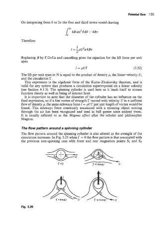
The flow pattern around a spinning cylinder
The flow pattern around the spinning cylinder is also altered as the strength of the
circulation increases. In Fig. 3.25 when r = 0 the flow pattern is that associated with
the previous non-spinning case with front and rear stagnation points S1 and S2
-* A&&
U
Fig. 3.25