
Page 199 - Aerodynamics for Engineering Students
P. 199
182 Aerodynamics for Engineering Students
experimental data, especially near the leading edge and near stagnation points where
the small perturbation theory, for example, breaks down. Any local inaccuracies tend
to vanish in the overall integration processes, however, and the aerofoil coefficients
are found to be reliable theoretical predictions.
'' 4.s The flapped aerofoil
Thin aerofoil theory lends itself very readily to aerofoils with variable camber such as
flapped aerofoils. The distribution of circulation along the camber line for the
general aerofoil has been found to consist of the sum of a component due to a flat
plate at incidence and a component due to the camber-line shape. It is sufficient for
the assumptions in the theory to consider the influence of a flap deflection as an
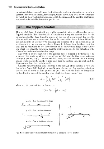
addition to the two components above. Figure 4.14 shows how the three contribu-
tions can be combined. In fact the deflection of the flap about a hinge in the camber
line effectively alters the camber so that the contribution due to flap deflection is the
effect of an additional camber-line shape.
The problem is thus reduced to the general case of finding a distribution to fit
a camber line made up of the chord of the aerofoil and the flap chord deflected
through 7 (see Fig. 4.15). The thin aerofoil theory does not require that the leading
and/or trailing edges be on the x axis, only that the surface slope is small and the
displacement from the x axis is small.
With the camber defined as hc the slope of the part AB of the aerofoil is zero, and
that of the flap - h/F. To find the coefficients of k for the flap camber, substitute
these values of slope in Eqns (4.41) and (4.42) but with the limits of integration
confined to the parts of the aerofoil over which the slopes occur. Thus
(4.48)
where q5 is the value of 0 at the hinge, i.e. C
----t +- 2
(1 -F)c=-(1 -cos$)
(a 1 Due to carnberline shape
y
-- -_
( c Due to incidence change
Fig. 4.14 Subdivision of lift contributions to total lift of cambered flapped aerofoil