
Page 390 - Air Pollution Control Engineering
P. 390
08_chap_wang.qxd 05/05/2004 4:26 pm Page 365
Thermal Oxidation 365
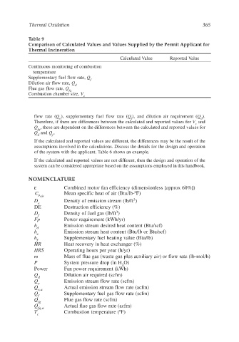
Table 9
Comparison of Calculated Values and Values Supplied by the Permit Applicant for
Thermal Incineration
Calculated Value Reported Value
Continuous monitoring of combustion
temperature
Supplementary fuel flow rate, Q
f
Dilution air flow rate, Q
d
Flue gas flow rate, Q
fg
Combustion chamber size, V
c
flow rate (Q ), supplementary fuel flow rate (Q ), and dilution air requirement (Q ).
e f d
Therefore, if there are differences between the calculated and reported values for V and
c
Q , these are dependent on the differences between the calculated and reported values for
fg
Q and Q .
d f
If the calculated and reported values are different, the differences may be the result of the
assumptions involved in the calculations. Discuss the details for the design and operation
of the system with the applicant. Table 6 shows an example.
If the calculated and reported values are not different, then the design and operation of the
system can be considered appropriate based on the assumptions employed in this handbook.
NOMENCLATURE
ε Combined motor fan efficiency (dimensionless [approx 60%])
C Mean specific heat of air (Btu/lb-ºF)
p air
3
D Density of emission stream (lb/ft )
e
DE Destruction efficiency (%)
3
D Density of fuel gas (lb/ft )
f
Fp Power requirement (kWh/yr)
h Emission stream desired heat content (Btu/scf)
d
h Emission stream heat content (Btu/lb or Btu/scf)
e
h Supplementary fuel heating value (Btu/lb)
f
HR Heat recovery in heat exchanger (%)
HRS Operating hours per year (h/yr)
m Mass of flue gas (waste gas plus auxiliary air) or flow rate (lb-mol/h)
P System pressure drop (in H O)
2
Power Fan power requirement (kWh)
Q Dilution air required (scfm)
d
Q Emission stream flow rate (scfm)
e
Q Actual emission stream flow rate (acfm)
e,a
Q Supplementary fuel gas flow rate (scfm)
f
Q Flue gas flow rate (scfm)
fg
Q Actual flue gas flow rate (acfm)
fg,a
T Combustion temperature (ºF)
c