
Page 395 - Air Pollution Control Engineering
P. 395
09_chap_wang.qxd 05/05/2004 5:01 pm Page 370
370 Lawrence K. Wang et al.
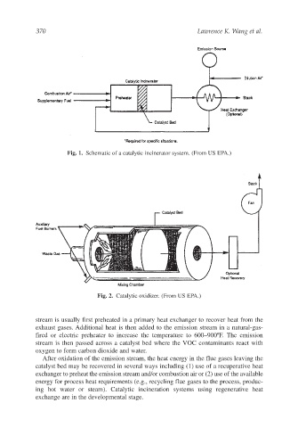
Fig. 1. Schematic of a catalytic incinerator system. (From US EPA.)
Fig. 2. Catalytic oxidizer. (From US EPA.)
stream is usually first preheated in a primary heat exchanger to recover heat from the
exhaust gases. Additional heat is then added to the emission stream in a natural-gas-
fired or electric preheater to increase the temperature to 600–900ºF. The emission
stream is then passed across a catalyst bed where the VOC contaminants react with
oxygen to form carbon dioxide and water.
After oxidation of the emission stream, the heat energy in the flue gases leaving the
catalyst bed may be recovered in several ways including (1) use of a recuperative heat
exchanger to preheat the emission stream and/or combustion air or (2) use of the available
energy for process heat requirements (e.g., recycling flue gases to the process, produc-
ing hot water or steam). Catalytic incineration systems using regenerative heat
exchange are in the developmental stage.