
Page 500 - Air Pollution Control Engineering
P. 500
12_ch_wang.qxd 05/05/2004 5:26 pm Page 472
472 Lawerence K. Wang et al.
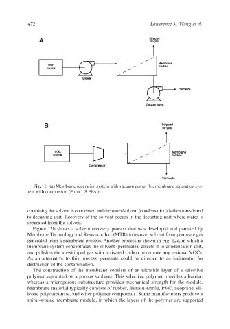
Fig. 11. (a) Membrane separation system with vacuum pump; (b), membrane separation sys-
tem with compressor. (From US EPA.)
containing the solvent is condensed and the water/solvent (condensation) is then transferred
to decanting unit. Recovery of the solvent occurs in the decanting unit where water is
separated from the solvent.
Figure 12b shows a solvent recovery process that was developed and patented by
Membrane Technology and Research, Inc. (MTR) to recover solvent from permeate gas
generated from a membrane process. Another process is shown in Fig. 12c, in which a
membrane system concentrates the solvent (permeate), directs it to condensation unit,
and polishes the air-stripped gas with activated carbon to remove any residual VOCs.
As an alternative to this process, permeate could be directed to an incinerator for
destruction of the contamination.
The construction of the membrane consists of an ultrathin layer of a selective
polymer supported on a porous sublayer. This selective polymer provides a barrier,
whereas a microporous substructure provides mechanical strength for the module.
Membrane material typically consists of rubber, Buna-n-nitrile, PVC, neoprene, sil-
icone polycarbonate, and other polymer compounds. Some manufacturers produce a
spiral-wound membrane module, in which the layers of the polymer are supported