
Page 129 - Air and Gas Drilling Manual
P. 129
maximum pressure capability of the compressor). The disadvantages are: 1) bulky,
2) high initial capital costs (relative to the rotary compressor of similar capabilities)
and, 3) relatively high maintenance costs due to greater number of moving parts
(relative to most rotary compressors). Chapter 4: Compressors 4-15
The main advantages of rotary compressors are: 1) initial low capital cost
(relative to reciprocating compressors), 2) less bulky (relative to the reciprocating
compressors of similar capabilities) and, 3) general ease of maintenance since these
compressors have few moving parts. The main disadvantages are: 1) cannot adjust
to flow line back pressures (fixed compression ratios), 2) needs frequent specific
maintenance of rotating wear surfaces to prevent slippage and, 3) most rotary
compressors operate with oil lubrication in the compression chambers [1, 2, 7].
4.5 Compressor Shaft Power Requirements
The most important single factor affecting the successful outcome of air and gas
drilling operations is the availability of constant, reliable volumetric flow rates of air
or gas to the well. This must be the case even when there are significant (and
frequent) changes in back pressure during these operations. The only two
compressor subclasses that can meet these flexibility requirements are the
reciprocating compressor and the rotary compressor. In what follows, the important
calculation techniques that allow for the proper evaluation and selection of the
appropriate compressors for air and gas drilling operations are reviewed [1, 7 and
10]. This section derives the theoretical power required at the compressor shaft to
compress the gas in the compressor.
4.5.1 Basic Single-Stage Shaft Power Requirement
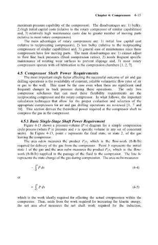
Figure 4-13 shows a pressure-volume (P-v) diagram for a simple compression
cycle process (where P is pressure and v is specific volume in any set of consistent
units). In Figure 4-13, point c represents the final state, or state 2, of the gas
leaving the compressor.
The area odcm measures the product P 2 v 2 which is the flow-work (ft-lb/lb)
required for delivery of the gas from the compressor. Point b represents the initial
state 1 of the gas and the area oabn measures the product P 1 v 1 which is the flow-
work (ft-lb/lb) supplied in the passage of the fluid to the compressor. The line bc
represents the state change of the gas during compression. The area mcbn measures
− 2 Pdv (4-4)
∫ 1
or
+ 1 Pdv (4-5)
∫ 2
which is the work ideally required for effecting the actual compression within the
compressor. Thus, aside from the work required for increasing the kinetic energy,
the net area abcd measures the net shaft work required for the induction,