
Page 203 - Air and Gas Drilling Manual
P. 203
Chapter 5: Shallow Well Drilling Applications 5-45
516
. )
.37
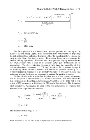
P in = (, 7 474 ) 2 + ( , 9 592 ) (516 37 2 e ) 2 (. 0 019 ) ( , 2 400 ) − 1 . 05
2
) ( , 2 400
(. 0 019
e 516 .37
2
P in = 21 350 lb/ft abs
,
P in
p in =
144
p in = 148 3 psia
.
The above pressure is the approximate injection pressure into the top of the
inside of the drill string. Again, these calculations have been carried out neglecting
the drill collar outside and inside diameters. Also, the calculations have ignored the
existence of a blooey line type structure. These minor losses are not important for
shallow drilling operations. Therefore, the above pressure slightly underestimates
the actual pressure that is seen at the pressure gauge just downstream of the
compressor. The above injection pressure is less than the capability of this
reciprocating piston compressor (i.e., 350 psig), therefore, the compressor is capable
of producing above injection pressure (the maximum pressure capability of a
reciprocating piston compressor is not derated with surface location elevation as long
as the prime mover has the power necessary to produce the required pressure).
The last criteria to check is whether the prime mover of this primary compressor
unit has the power to operate at the 4,000 ft surface elevation. The prime mover for
this compressor is a diesel fueled, turbocharged, Caterpillar Model D353 with a peak
output of 270 horsepower at 1,000 rpm (at API standard conditions). The theoretical
˙
shaft horsepower, W , required by each of the two compressors is obtained from
s
Equation 4-35. Equation 4-35 becomes
, 1 400
04
(.685 ) (. )
12
.
2
() ( . ) 4 2 148 3 ()( . )
1
21
4
˙
W = − 1
s
(.) 229 .17 12 .685
04
˙
W = 114 .1
s
The mechanical efficiency, ε , is
v
ε m = 090
.
From Equation 4-37, the first stage compression ratio of the compressor is