
Page 38 - Air and Gas Drilling Manual
P. 38
Chapter 1: Introduction 1-15
In the past decade it has been observed that drilling with a circulation fluid that
has a bottomhole pressure slightly below that of the pore pressure of the fluid
deposit gives near optimum results. This type of drilling is denoted as underbalanced
drilling. Underbalanced drilling allows the formation to produce fluid as the drilling
progresses. This lowers or eliminates the risk of formation damage and eliminates
the possibility of formation fracture and loss of circulation. In general, if the pore
pressure of a deposit is high, an engineered adjustment to the drilling mud weight
(with additives) can yield the appropriate drilling fluid to assure underbalanced
drilling. However, if the pore pressure is not unusually high then air and gas drilling
techniques are required to lighten the drilling fluid column in the annulus.
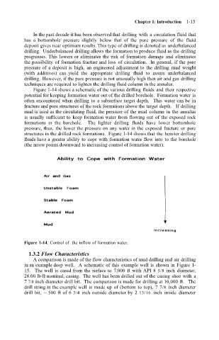
Figure 1-14 shows a schematic of the various drilling fluids and their respective
potential for keeping formation water out of the drilled borehole. Formation water is
often encountered when drilling to a subsurface target depth. This water can be in
fracture and pore structures of the rock formations above the target depth. If drilling
mud is used as the circulating fluid, the pressure of the mud column in the annulus
is usually sufficient to keep formation water from flowing out of the exposed rock
formations in the borehole. The lighter drilling fluids have lower bottomhole
pressure, thus, the lower the pressure on any water in the exposed fracture or pore
structures in the drilled rock formations. Figure 1-14 shows that the heavier drilling
fluids have a greater ability to cope with formation water flow into to the borehole
(the arrow points downward to increasing control of formation water).
Figure 1-14: Control of the inflow of formation water.
1.3.2 Flow Characteristics
A comparison is made of the flow characteristics of mud drilling and air drilling
in an example deep well. A schematic of this example well is shown in Figure 1-
15. The well is cased from the surface to 7,000 ft with API 8 5/8 inch diameter,
28.00 lb/ft nominal, casing. The well has been drilled out of the casing shoe with a
7 7/8 inch diameter drill bit. The comparison is made for drilling at 10,000 ft. The
drill string in the example well is made up of (bottom to top), 7 7/8 inch diameter
drill bit, ~ 500 ft of 6 3/4 inch outside diameter by 2 13/16 inch inside diameter