
Page 595 - Air and Gas Drilling Manual
P. 595
Chapter 11: Specialized Drilling Equipment 11-33
MWD system made up above the bent sub. The conventional drill string is made up
to the top of the MWD.
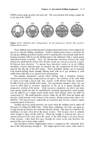
Figure 11-11: Different lobe configurations for the progressive helical lobe positive
displacement motors.
These drilling mud actuated positive displacement motors have been adapted for
use in air and gas drilling operations. Positive displacement motors converted for
air and gas drilling operations usually involve replacing the conventional mud motor
bearing assembly (which uses the drilling mud as the lubricant) with a sealed grease
lubricated bearing assembly. Also, the dimensional tolerances between the rigid
helical lobe shaft and the helical lobe flexible sheath are relaxed to provide a looser
fit between these elements. To operate these downhole motors in an air drilling
operation, a liquid lubricant must be injected into the compressed air flow being
injected into the top of the drill string. These downhole motors can be operated
with aerated drilling fluids (usually drilling mud with air or gas aeration) or with
stable foam with little or no special motor preparations.
The primary operational concern when drilling with a downhole positive
displacement motor using compressed air (or gas) is the tendency of the rotor shaft
to rotate at too high a speed and, thus, destroy (with friction heat) the elastomer
flexible helical cavity sheath of the motor. One operational situation where this can
occur is when there is excessive expansion of the air as it passes through the
progressive cavities of the motor. Such excessive expansion can allow run away
rotor speeds which can only be controlled by inserting appropriately sized nozzles
into the drill bit (or a single nozzle inside motor flow passage above the drill bit
connection) [3]. The small diameter nozzles choke the air flow from the motor and
provide a back pressure at the bottom of the positive displacement motor (above the
drill bit). This back pressure controls the air expansion and, thereby, controls output
rotational speed of the rotor.
Another run away speed situation can occur when the drilling load is taken off
the motor by lifting the drill string. Under these conditions, the rotor can again go
to high speeds and destroy the elastomer flexible sheath. This must be controlled by
installing a by-pass valve above the motor section. This by-pass valve is actuated
when weight is taken off the drill bit. When the weight is removed the valve is
opened and most of the flow down the inside of the drill string is diverted directly
to the annulus. Little fluid flow goes through the motor cavity and, therefore, the
speed of the rotor is kept under control.
The downhole positive displacement motor is actuated by the volumetric flow
rate of the fluid passing through it. The output speed of the motor rotor shaft is