
Page 619 - Air and Gas Drilling Manual
P. 619
Chapter 11: Specialized Drilling Equipment 11-57
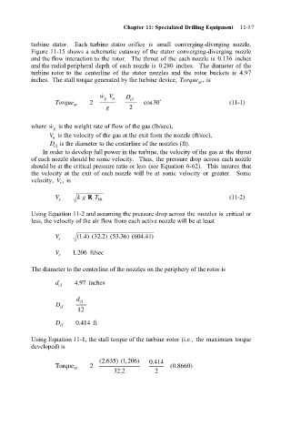
turbine stator. Each turbine stator orifice is small converging-diverging nozzle.
Figure 11-15 shows a schematic cutaway of the stator converging-diverging nozzle
and the flow interaction to the rotor. The throat of the each nozzle is 0.136 inches
and the radial peripheral depth of each nozzle is 0.280 inches. The diameter of the
turbine rotor to the centerline of the stator nozzles and the rotor buckets is 4.97
inches. The stall torque generated by the turbine device, Torque , is
sr
˙
wV n D cl
g
Torque 2 cos 30˚ (11-1)
sr
g 2
where ˙ w is the weight rate of flow of the gas (lb/sec),
g
V is the velocity of the gas at the exit from the nozzle (ft/sec),
n
D is the diameter to the centerline of the nozzles (ft).
cl
In order to develop full power in the turbine, the velocity of the gas at the throat
of each nozzle should be sonic velocity. Thus, the pressure drop across each nozzle
should be at the critical pressure ratio or less (see Equation 6-62). This insures that
the velocity at the exit of each nozzle will be at sonic velocity or greater. Sonic
velocity, V , is
s
V s k g R T bh (11-2)
Using Equation 11-2 and assuming the pressure drop across the nozzles is critical or
less, the velocity of the air flow from each active nozzle will be at least
1
41
4
V s ( . )(32 . )(53 .36 )(604 . )
2
,
V 1 206 ft/sec
s
The diameter to the centerline of the nozzles on the periphery of the rotor is
.
d cl 497 inches
d cl
D
cl
12
D cl 0 414 ft
.
Using Equation 11-1, the stall torque of the turbine rotor (i.e., the maximum torque
developed) is
2 635) ( ,
(. 1 206) 0 414
.
0 8660)
Torque sr 2 (.
32 2 . 2