Page 631 - Air and Gas Drilling Manual
P. 631
Chapter 11: Specialized Drilling Equipment    11-69
                                                         2
                                                              2 635)
                                             .
                                             0 016
                                                    53 36
                                                      .
                                      b
                                       i1
                                                              2
                                            232 2 . )
                                                     10 .
                                             (
                                                                0 319)
                                                            4 (.  (.  2  5
                                            ,
                                      b i1  2 486
                               Equation 6-72 becomes
                                                                                      . 05
                                                                       2  (. 0 019 ) ( , 6 650 )
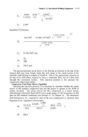
                                            (,370 ) 2  ( , 2 486 ) (537 .66 ) 2  e  537 .66  1
                                             61
                                      P in                  2  (. 0 019 ) ( , 6 650 )
                                                           e   537 .66
                                                     2
                                             ,
                                      P in  51 340 lb/ft abs
                                            P in
                                      p in
                                            144
                                      p in  356 5 psia
                                              .
                                   The injection pressure given above is  the flowing air pressure at the top  of the
                               lumped drill  pipe  body  length  inside  the  drill  string  in  the  cased  section  of  the
                               borehole while drilling at a depth of 10,000 ft.  This  is  the approximate injection at
                               the top  of the drill  string  required  to  force  a  volumetric  flow  rate  of  2,400  acfm
                               through  the  circulation  system.    This  injection  pressure  is  the  pressure  the
                               compressor output must match.
                                 Compressor Unit Prime Mover Capability
                                   Knowing the injection pressure, it  is  necessary to  ascertain  whether  the  prime
                               mover  of  this  primary  compressor  unit  has  the  power  to  operate  at  the  4,000  ft
                               surface  elevation.    The  prime  mover  for  this  compressor  is  a  diesel  fueled,
                               turbocharged, Caterpillar Model D398 with a peak output  of 760 horsepower at 900
                               rpm (at API standard conditions) (see Section  4.7  in  Chapter  4).    The  theoretical
                                              ˙
                               shaft horsepower,  W ,  required  by  each  of  the  two  compressors  is  obtained  from
                                               s
                               Equation 4-35a.  Equation 4-35a becomes
                                                            , 2 400
                                                                           04
                                                    12
                                                   (.685 )                (. )
                                            4
                                            () ( . ) 4       2      356 .5  ()( . )
                                               1
                                                                          41
                                                                             4
                                      W ˙  s                                    1
                                             (.)        229 .17    12 .685
                                              04
                                      W ˙  s  250 .2

