
Page 155 - Air and gas Drilling Field Guide 3rd Edition
P. 155
146 CHAPTER 6 Direct Circulation Models
P (All)
in
P e
P
d P
P bca
H
P bdpi
P bdpa
P bdci
P
P bdca =P bh ai
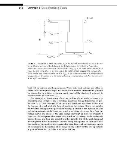
FIGURE 6-1. Schematic of direct circulation. P in is the injection pressure into the top of the drill
string, P bdpi is pressure at the bottom of the drill pipe inside the drill string, P bdci is the
pressure at the bottom of drill collars inside the drill string, P ai is the pressure above the drill bit
inside the drill string, P bdca is the pressure at the bottom of drill collars in the annulus, P bh
is the bottom hole pressure in the annulus, P bdpa is the pressure at bottom of drill pipe in the
annulus, P bca is the pressure at the bottom of casing in the annulus, and P e is the pressure
at the top of the annulus.
fluid will be uniform and homogeneous. When solid rock cuttings are added to
the mixture of compressible gas and incompressible fluid, the solid rock particles
are assumed to be uniform in size and density and will be distributed uniformly in
the mixture of gas and fluid [1].
The assumption of uniformity of the two or three phases in the mixtures is an
important issue in light of the technology developed for gas lift-assisted oil pro-
duction [2, 3]. The aeration of oil (or other formation produced fluids) from
the bottom of a well with the flow of gas from the surface (down the annulus
between the casing and the production tubing) is similar to the aeration of fluid
and rock cuttings from the bottom of a well with a flow of gas and fluid from the
surface (down the inside of the drill string). However, in most oil production
situations, the two-phase flow takes place inside of the tubing. In the drilling sit-
uation, the gas and fluid are injected together into the top of the drill string and
move together down the inside of the drill string, through the bit orifices or noz-
zles, and then the resulting three-phase flow (gas, fluid, and rock cuttings) moves
up the annulus to the surface. Thus, the geometry of flow for the two operations
is quite different and probably not comparable [4].