
Page 150 - Air and gas Drilling Field Guide 3rd Edition
P. 150
5.8 Membrane Field Nitrogen Generator 141
must be matched with a variety of primary compressors that feed the units with
compressed atmospheric air.
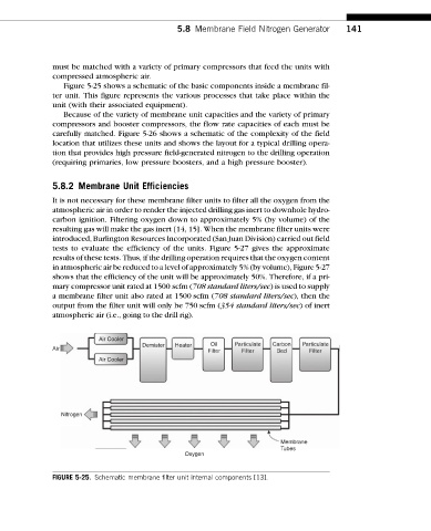
Figure 5-25 shows a schematic of the basic components inside a membrane fil-
ter unit. This figure represents the various processes that take place within the
unit (with their associated equipment).
Because of the variety of membrane unit capacities and the variety of primary
compressors and booster compressors, the flow rate capacities of each must be
carefully matched. Figure 5-26 shows a schematic of the complexity of the field
location that utilizes these units and shows the layout for a typical drilling opera-
tion that provides high pressure field-generated nitrogen to the drilling operation
(requiring primaries, low pressure boosters, and a high pressure booster).
5.8.2 Membrane Unit Efficiencies
It is not necessary for these membrane filter units to filter all the oxygen from the
atmospheric air in order to render the injected drilling gas inert to downhole hydro-
carbon ignition. Filtering oxygen down to approximately 5% (by volume) of the
resulting gas will make the gas inert [14, 15]. When the membrane filter units were
introduced, Burlington Resources Incorporated (San Juan Division) carried out field
tests to evaluate the efficiency of the units. Figure 5-27 gives the approximate
results of these tests. Thus, if the drilling operation requires that the oxygen content
in atmospheric air be reduced to a level of approximately 5% (by volume), Figure 5-27
shows that the efficiency of the unit will be approximately 50%. Therefore, if a pri-
mary compressor unit rated at 1500 scfm (708 standard liters/sec) is used to supply
a membrane filter unit also rated at 1500 scfm (708 standard liters/sec), then the
output from the filter unit will only be 750 scfm (354 standard liters/sec) of inert
atmospheric air (i.e., going to the drill rig).
Air Cooler
Demister Heater Oil Particulate Carbon Particulate
Air
Filter Filter Bed Filter
Air Cooler
Nitrogen
Membrane
Tubes
Oxygen
FIGURE 5-25. Schematic membrane filter unit internal components [13].