
Page 200 - Air and gas Drilling Field Guide 3rd Edition
P. 200
8.2 Minimum Volumetric Flow Rate and Compressor Selection 191
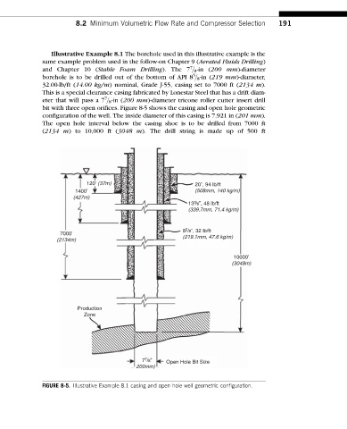
Illustrative Example 8.1 The borehole used in this illustrative example is the
same example problem used in the follow-on Chapter 9 (Aerated Fluids Drilling)
7
and Chapter 10 (Stable Foam Drilling). The 7 8 = -in (200 mm)-diameter
5
borehole is to be drilled out of the bottom of API 8 8 = -in (219 mm)-diameter,
32.00-lb/ft (14.00 kg/m) nominal, Grade J-55, casing set to 7000 ft (2134 m).
This is a special clearance casing fabricated by Lonestar Steel that has a drift diam-
7
eter that will pass a 7 8 = -in (200 mm)-diameter tricone roller cutter insert drill
bit with three open orifices. Figure 8-5 shows the casing and open hole geometric
configuration of the well. The inside diameter of this casing is 7.921 in (201 mm).
The open hole interval below the casing shoe is to be drilled from 7000 ft
(2134 m) to 10,000 ft (3048 m). The drill string is made up of 500 ft
120’ (37m) 20”, 94 lb/ft
1400’ (508mm, 140 kg/m)
(427m)
13 3 /8”, 48 lb/ft
(339.7mm, 71.4 kg/m)
8 5 /8”, 32 lb/ft
7000’ (219.1mm, 47.6 kg/m)
(2134m)
10000’
(3048m)
Production
Zone
7 7 /8” Open Hole Bit Size
200mm)
FIGURE 8-5. Illustrative Example 8.1 casing and open hole well geometric configuration.