
Page 207 - Air and gas Drilling Field Guide 3rd Edition
P. 207
198 CHAPTER 8 Air, Gas, and Unstable Foam Drilling
the top of the annulus into the blooey line and to include losses due to the two
blooey line valves at the entrance end of the line. Therefore, the equation for the
pressure in the air (or gas) flow at the entrance end of the blooey line P b can
be approximated as
" ! # 0:5
2
g
L b w R T r 2
P b ¼ f b þ K t þ S K v 2 þ P at ; (8-2)
D b gA S g
b
where f b is the friction factor for gas flow in the blooey line, L b is the length of
the blooey line (ft, m), D b is the inside diameter of the blooey line (ft, m), A b is
2
2
the cross-sectional area of the inside of the blooey line (ft ,m ), K t is the minor
loss factor for the T turn at the top of the annulus, and K v is the minor loss factor
for the valves in the blooey line.
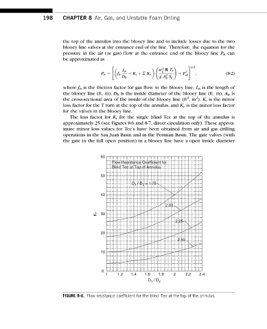
The loss factor for K t for the single blind Tee at the top of the annulus is
approximately 25 (see Figures 8-6 and 8-7, direct circulation only). These approx-
imate minor loss values for Tee’s have been obtained from air and gas drilling
operations in the San Juan Basin and in the Permian Basin. The gate valves (with
the gate in the full open position) in a blooey line have a open inside diameter
60
Flow Resistance Coefficient for
Blind Tee at Top of Annulus
50
D / D = 1.75
1
3
40
2.00
K T 30
2.25
20
2.50
10
0
1 1.2 1.4 1.6 1.8 2 2.2 2.4
D 1 / D 2
FIGURE 8-6. Flow resistance coefficient for the blind Tee at the top of the annulus.