
Page 210 - Air and gas Drilling Field Guide 3rd Edition
P. 210
8.3 Bottom Hole and Injection Pressures 201
8.3 BOTTOM HOLE AND INJECTION PRESSURES
The aforementioned sections compared the borehole requirements with the
compressor capabilities of the compressor packages available in Chapter 5,
Section 5.7. The next step in the planning process is to determine the air flow
pressure values throughout the circulating system, particularly the bottom hole
annulus pressure and the surface injection pressure.
Illustrative Example 8.3 Here again, the basic drilling project well data given
in Illustrative Example 8.1 and Illustrative Example 8.2 are used to determine the
pressures in the example circulation system. In Illustrative Example 8.2 it was
found that two Dresser Clark CFB-4 primary compressors would give the drilling
project an appropriate factor of safety with regards to air volumetric flow rate.
Therefore, the pressures will be determined using an air volumetric flow rate of
2400 acfm (1132.7 actual liters/sec).
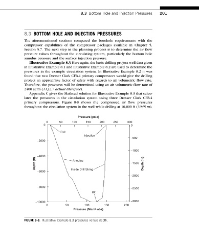
Appendix C gives the Mathcad solution for Illustrative Example 8.3 that calcu-
lates the pressures in the circulation system using three Dresser Clark CFB-4
primary compressors. Figure 8-8 shows the compressed air flow pressures
throughout the circulation system in the well while drilling at 10,000 ft (3048 m).
Pressure (psia)
0 50 100 150 200 250 300
0 0
Exit
Injection
−500
−2000
−1000
Depth (ft) −4000 Annulus −1500 Depth (m)
−6000 Inside Drill String
−2000
−8000
−2500
Bit
−10000 −3000
0 50 100 150 200
Pressure (N/cm 2 abs)
FIGURE 8-8. Illustrative Example 8.3 pressures versus depth.