
Page 149 - Aircraft Stuctures for Engineering Student
P. 149
5.3 Distributed transverse load 133
5.3.2 The built-in edge
_1___1_1__
If the edge x = 0 is built-in or firmly clamped so that it can neither rotate nor deflect,
then, in addition to MI, the slope of the middle plane of the plate normal to this edge
must be zero. That is
(5.24)
5.3.3 The free edge
Along a free edge there are no bending moments, twisting moments or vertical
shearing forces, so that if x = 0 is the free edge then
(MJx=o = 0, (Mxy)x=o = 0, (QX),=o = 0
giving, in this instance, three boundary conditions. However, Kirchhoff (1850)
showed that only two boundary conditions are necessary to obtain a solution of
Eq. (5.20), and that the reduction is obtained by replacing the two requirements of
zero twisting moment and zero shear force by a single equivalent condition. Thomson
and Tait (1883) gave a physical explanation of how this reduction may be effected.
They pointed out that the horizontal force system equilibrating the twisting
moment Mxy may be replaced along the edge of the plate by a vertical force system.
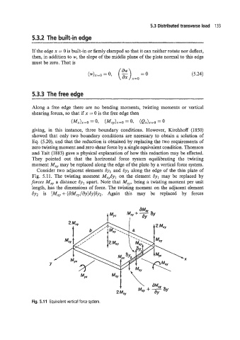
Consider two adjacent elements Syl and Sy2 along the edge of the thin plate of
Fig. 5.1 1. The twisting moment Mx,,6yl on the element byl may be replaced by
forces Mxy a distance Syl apart. Note that Mxy, being a twisting moment per unit
length, has the dimensions of force. The twisting moment on the adjacent element
Sy2 is [Mxy+ (aMxy/dy)Gy]by2. Again this may be replaced by forces
X
Y
Fig. 5.1 1 Equivalent vertical force system.