
Page 271 - Aircraft Stuctures for Engineering Student
P. 271
252 Airworthiness and airframe loads
Gust gradient distance
(b)
T 2T t
(C)
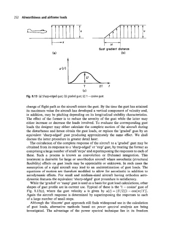
Fig. 8.13 (a) Sharp-edged gust; (b) graded gust; (c) 1 - cosine gust.
change of flight path as the aircraft enters the gust. By the time the gust has attained
its maximum value the aircraft has developed a vertical component of velocity and,
in addition, may be pitching depending on its longitudinal stability characteristics.
The effect of the former is to reduce the severity of the gust while the latter may
either increase or decrease the loads involved. To evaluate the corresponding gust
loads the designer may either calculate the complete motion of the aircraft during
the disturbance and hence obtain the gust loads, or replace the ‘graded‘ gust by an
equivalent ‘sharp-edged’ gust producing approximately the same effect. We shall
discuss the latter procedure in greater detail later.
The calculation of the complete response of the aircraft to a ‘graded’ gust may be
obtained from its response to a ‘sharp-edged’ or ‘step’ gust, by treating the former as
comprising a large number of small ‘steps’ and superimposing the responses to each of
these. Such a process is known as convolution or Duhamel integration. This
treatment is desirable for large or unorthodox aircraft where aeroelastic (structural
flexibility) effects on gust loads may be appreciable or unknown. In such cases the
assumption of a rigid aircraft may lead to an underestimation of gust loads. The
equations of motion are therefore modified to allow for aeroelastic in addition to
aerodynamic effects. For small and medium-sized aircraft having orthodox aero-
dynamic features the equivalent ‘sharp-edged’ gust procedure is satisfactory.
While the ‘graded’ or ‘ramp’ gust is used as a basis for gust load calculations, other
shapes of gust profile are in current use. Typical of these is the ‘1 - cosine’ gust of
Fig. 8.13(c), where the gust velocity u is given by u(t) = (U/2)[1 - cos(~t/T)].
Again the aircraft response is determined by superimposing the responses to each
of a large number of small steps.
Although the ‘discrete’ gust approach still finds widespread use in the calculation
of gust loads, alternative methods based on power spectrd analysis are being
investigated. The advantage of the power spectral technique lies in its freedom