
Page 275 - Aircraft Stuctures for Engineering Student
P. 275
256 Airworthiness and airframe loads
I
E
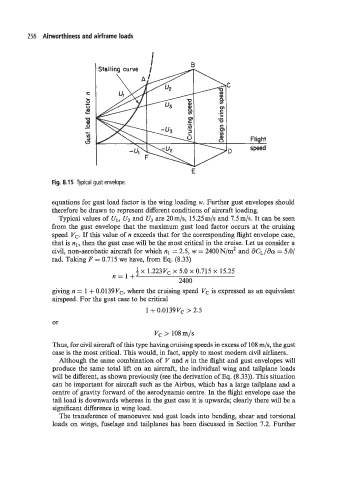
Fig. 8.15 Typical gust envelope.
equations for gust load factor is the wing loading w. Further gust envelopes should
therefore be drawn to represent different conditions of aircraft loading.
Typical values of U1, U2 and U, are 20m/s, 15.25m/s and 7.5m/s. It can be seen
from the gust envelope that the maximum gust load factor occurs at the cruising
speed Vc. If this value of n exceeds that for the corresponding fight envelope case,
that is nl, then the gust case will be the most critical in the cruise. Let us consider a
civil, non-aerobatic aircraft for which nl = 2.5, w = 2400N/m2 and aCL/acw = 5.0/
rad. Taking F = 0.715 we have, from Eq. (8.33)
!j x 1.223Vc x 5.0 x 0.715 x 15.25
n=l+
2400
giving n = 1 + 0.0139Vc, where the cruising speed Vc is expressed as an equivalent
airspeed. For the gust case to be critical
1 + 0.0139Vc > 2.5
or
Vc > 108m/s
Thus, for civil aircraft of this type having cruising speeds in excess of 108 m/s, the gust
case is the most critical. This would, in fact, apply to most modern civil airliners.
Although the same combination of V and n in the flight and gust envelopes will
produce the same total lift on an aircraft, the individual wing and tailplane loads
will be different, as shown previously (see the derivation of Eq. (8.33)). This situation
can be important for aircraft such as the Airbus, which has a large tailplane and a
centre of gravity forward of the aerodynamic centre. In the aght envelope case the
tail load is downwards whereas in the gust case it is upwards; clearly there will be a
sign5cant difference in wing load.
The transference of manoeuvre and gust loads into bending, shear and torsional
loads on wings, fuselage and tailplanes has been discussed in Section 7.2. Further