
Page 501 - Aircraft Stuctures for Engineering Student
P. 501
482 Structural constraint
The second two terms on the right-hand side of Eq. (1 1.75) give the direct stress due to
bending as predicted by elementary beam theory (see Eq. (9.6)); note that the above
approach provides an alternative method of derivation of Eq. (9.6).
Comparing the last term on the right-hand side of Eq. (1 1.75) with Eq. (1 1.54), we
see that
Se
~AR Uz 2A~t ds
= Or
rR
It follows therefore that the external application of a direct stress system a, induces a
self-equilibrating direct stress system Or. Also, the first differential of the rate of twist
(d26/dzz) is related to the applied a, stress system through the term Jeaz2ARtds.
Thus, if sc az2ARt ds is interpreted in terms of the applied loads at a particular section
then a boundary condition exists (for d26/d2) which determines one of the constants
in the solution of either Eq. (1 1.59) or Eq. (1 1.64).
11.5.3 Moment couple (bimoment)
The units of sc a,2ARtds are force x (distance)2 or moment x distance. A simple
physical representation of this expression would thus consist of two equal and
opposite moments applied in parallel planes some distance apart. This combination
has been termed a moment couple’ or a bimoment3 and is given the symbol Mr or
B,. Equation (11.75) is then written
p (My Ixx - MxLy MXIYY - MYIXY M~~AR
a,=-+ (1 1.76)
A IxxIyy - Ix:, >,+ ( IxxIyy - I2y ) Y + T
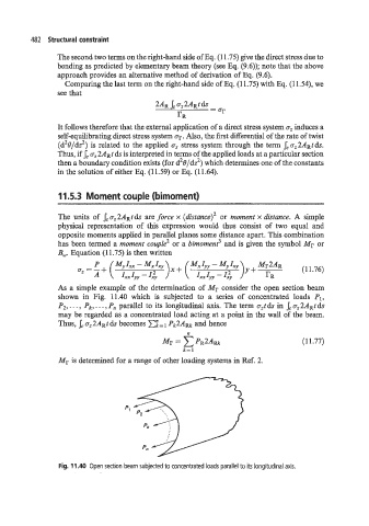
As a simple example of the determination of Mr consider the open section beam
shown in Fig. 11.40 which is subjected to a series of concentrated loads PI,
P2,. . . , Pk, . . . , Pn parallel to its longitudinal axis. The term azt ds in Jc a,2ARt ds
may be regarded as a concentrated load acting at a point in the wall of the beam.
Thus, Sc az2ARt ds becomes E;= Pk2Aw, and hence
n
(1 1.77)
Mr is determined for a range of other loading systems in Ref. 2.
Fig. 11.40 Open section beam subjected to concentrated loads parallel to its longitudinal axis.