
Page 82 -
P. 82
56 Chapter 2 ■ Edge-Detection Techniques
The following is the basic code for applying the Sobel algorithm to each
color channel:
if(get_RGB(&x, &y, &z, image_name))
{
sobel (x);
sobel (y);
sobel (z);
for (i=0; i<x->info->nr; i++)
for (j=0; j<x->info->nc; j++)
x->data[i][j] = 255 - (x->data[i][j]+y->data[i][j] +
z->data[i][j])/3;
save_iamge (x, out_name);
}
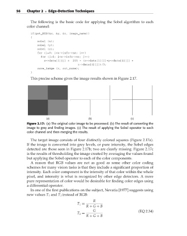
This precise scheme gives the image results shown in Figure 2.17.
(a) (b) (c)
Figure 2.17: (a) The original color image to be processed. (b) The result of converting the
image to grey and finding images. (c) The result of applying the Sobel operator to each
color channel and then merging the results.
The target image consists of four distinctly colored squares (Figure 2.17a).
If the image is converted into grey levels, or pure intensity, the Sobel edges
detected are those seen in Figure 2.17b; two are clearly missing. Figure 2.17c
is the results of thresholding the image created by averaging the values found
but applying the Sobel operator to each of the color components.
A reason that RGB values are not as good as some other color coding
schemes for many vision tasks is that they include a significant proportion of
intensity. Each color component is the intensity of that color within the whole
pixel, and intensity is what is recognized by other edge detectors. A more
pure representation of color would be desirable for finding color edges using
a differential operator.
In one of the first publications on the subject, Nevatia [1977] suggests using
new values T 1 and T 2 instead of RGB:
R
T 1 =
R + G + B
G (EQ 2.34)
T 2 =
R + G + B