Page 117 - Alternative Energy Systems in Building Design
P. 117

SOLAR POWER SYSTEM CONFIGURATIONS   93


                                                         SURGE SPIKE WITH DELTA SURGE
                                           HARMFUL           ARRESTOR/SUPRESSOR
                                           SURGE SPIKE
                                                                           CLAMPING (SUPRESSION)
                                                                           VOLTAGE


                                                           LINE
                         LINE                            VOLTAGE
                       VOLTAGE


                                                                         (b)
                                        (a)

                                                       SURGE SPIKE WITH
                                                    DELTA SURGE CAPACITOR


                                               LINE
                                             VOLTAGE


                                                             (c)
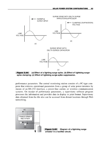
                        Figure 3.44  (a) Effect of a lighting surge spike. (b) Effect of lightning surge-
                        spike clamping. (c) Effect of lightning surge-spike suppression.


                       performance parameters. The central monitoring station consists of a PC-type com-
                       puter that retrieves operational parameters from a group of solar power inverters by
                       means of an RS-232 interface, a power-line carrier, or wireless communication
                       systems. On receipt of performance parameters, a supervisory software program
                       processes the information and provides data in display or print format. Supervisory
                       data obtained from the file also can be accessed from distant locations through Web
                       networking.


                              AC


                         TRANSFORMER
                           RECTIFIER
                           +
                               –
                              DC
                                                  Figure 3.45   Diagram of a lightning surge
                                                  arrestor in a rectifier circuit.
   112   113   114   115   116   117   118   119   120   121   122